STEERING COLUMN SWITCH UNIT MODULE
Introduction
The steering column switch unit basically groups the following functions together:
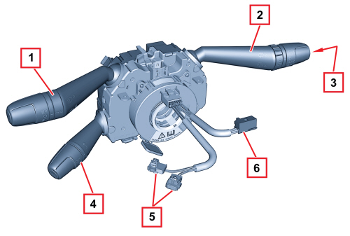
1. Lever for exterior lights
2. Lever for windscreen washing and wiping functions
3. TRIP function button
4. Cruise Control lever (if present)
5. Air Bag connectors
6. Horn connector and controls on the steering wheel
The steering column switch unit module is composed of a maximum of three levers (lights, wiper and Cruise Control), an electronic module (that manages the motor for the windscreen wipers and the windscreen washer pump) and a clock spring that produces the connection with the steering wheel.
The electronic module controls the wiping functions, in particular:
- windscreen wiper: sweep rate;
- rear screen wiper: sweep rate and control during reversing;
- windscreen wiper function: smart washing;
- rear screen washer function: smart washing;
- rain sensor: managed by a signal from the sensor (if present).
The clock spring has two functions:
- transmitting the rotation of the steering wheel to the automatic release mechanism located inside the casing;
- transferring the electrical signal for the controls on the steering wheel (horn, radio controls) and the Air Bag module
Operation
Left lever
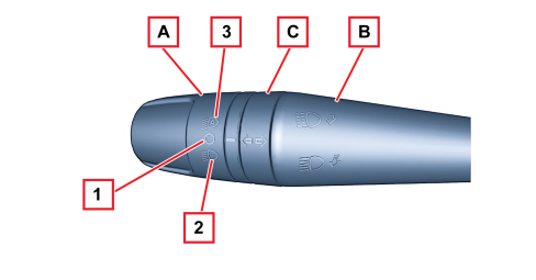
A - Lights selector
B - Lights flasher - main beam headlamps switch
C - Direction indicators
The lights selector is a ring nut with 3 stable positions on the end of the lever and it is activated by turning it around the actual lever axis:
- Pos. 1 = No circuit on: daytime lights operation
- Pos. 2 - Dipped headlamps
- Pos. 3 = Auto function for dipped headlamps (where dusk sensor is fitted)
DAYTIME LIGHTS
With the key in the ON position and the ring nut in position "O" the daytime lights come on automatically; the other lights and the interior lighting remain off.

|
The automatic switching on of the daytime lights can be activated/deactivated using the menu in the instrument panel; if the daytime lights are deactivated, none of the lights come on with the ring nut in position O. |
DIPPED HEADLAMPS/SIDE LIGHTS
With the ignition in the ON position, when the ring nut is turned forwards the dipped headlamps are activated, the daytime lights go out and the side lights, dipped headlamps and number plate lights are turned on.
The side lights warning light in the instrument panel lights up.
With the ignition key in the OFF position or extracted, all the side lights and number plate lights come on when the ring nut is turned forwards. The side lights warning light in the instrument panel lights up.
Parking function
With the side lights on and the ignition key in the OFF position or extracted, it is possible to select the lighting on the desired side by operating the lights lever downwards (left side) or upwards (right side). In this case the side lights warning light in the instrument panel will go out.
DUSK SENSOR:
On some versions, the lights are also activated automatically by the dusk sensor.
This sensor, located on the windscreen under the interior rear view mirror, detects the variations in outside brightness depending on the light setting: the greater the sensitivity, the less external light is required to activate the exterior lights.
The setting of the dusk sensor can be adjusted using the instrument panel setup menu.
If a fault is detected with the dusk sensor, the "general failure" warning light is turned on and the information is shown simultaneously on the display.
Follow me home:
The follow me home function allows the dipped headlights and the side lights to remain on even after the engine has been switched off (key in OFF position or extracted) for a period of 30 seconds or multiples thereof. The side lights warning light in the instrument panel signals that the lights have remained on. It is turned on using the lever in the same way as for activating the flasher within 2 minutes of the ignition being switched OFF: each time the lever is operated the length of time the lights remain on is increased by 30 seconds, up to a maximum of 210 seconds. Turning the key to the ON position or keeping the flasher lever pulled for more than 2 seconds eliminates the function.
MAIN BEAMS
The flasher control is produced by pulling the lever from the rest position towards the steering wheel; the activation is unstable because when the lever is released it returns to the rest position. The constant main beams control is produced by pushing the lever towards the dashboard.
DIRECTION INDICATORS
The command for the direction indicators is produced by moving the lever on the steering wheel plane in both directions, upwards for the right direction indicators and downwards for the left ones.
The lever has two distinct activating modes: one unstable one known as "changing lane" and one stable one known as "changing direction".
The stable activation is provided by an automatic release device which returns the lever to the rest position once the manoeuvre has been carried out (turning the steering wheel in the same direction as the lever).
The unstable activation on the release of the lever reopens the electrical contact that has closed.
Lane change function:
When the left lever is placed in an unstable position for less than half a second, the direction indicator on the side selected is activated for 5 flashes and then goes out automatically.
Right lever
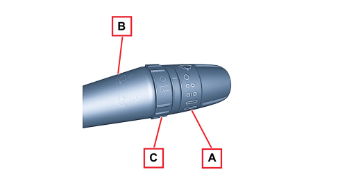
A - Windscreen wiper intermittent operation / rain sensor setting (if present) selector;
B - Windscreen washer / rear screen washer;
C - Rear screen wiper;
The windscreen wiper is operated by moving the lever along the plane of the steering wheel.
There are 5 different activation positions, from the top, in this order:
- Temporary speed operation (unstable)
- OFF
- Intermittent/automatic operation
- Continuous slow operation
- Continuous fast operation
WINDSCREEN WIPER INTERMITTENT SELECTOR (RAIN SENSOR SETTING)
The adjustment takes place by turning the ring nut into 4 stable positions.
4 different pause times for the intermittent operation of the windscreen wiper correspond to these positions.
If a rain sensor is fitted, the positions correspond to the 4 rain sensor settings.
WINDSCREEN WASHER/REAR SCREEN WASHER CONTROL
The control for activating the two-way pump for washing the front windscreen is produced by pulling the lever towards the steering wheel crown; the activation is unstable.
The control for activating the two-way pump for washing the rear screen is produced by pulling the lever towards the dashboard; the activation is unstable.
REAR WIPER CONTROL
The rear screen wiper is controlled by rotating a ring nut in 2 stable positions halfway along the lever.
TRIP BUTTON
By pressing the unstable TRIP button on the lever the relevant commands are sent to the instrument panel.
Cruise control lever
See
See descriptions 5580A CRUISE CONTROL SYSTEM
Components
Control electronics
The electronics for controlling the windscreen and rear screen wiper and washer functions are housed inside the steering column switch unit and are capable of controlling the windscreen and rear screen wiper motors and the two-way pump.
By means of the A-BUS interface it is capable of conversing with the rain sensor and, as a result, of controlling the windscreen wiper in automatic mode (refer to the A-BUS serial network and the rain sensor).
For more details on the wiping logic,
See descriptions 5050 SCREEN WASHER AND HEADLAMP WASH/WIPE
Electrical connections
The steering column switch unit is connected to the vehicle wiring by means of a single connector.
All the signals sent are the digital type so that multiple information is sent through a single connection.
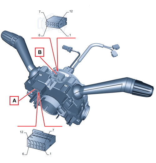
- connector A: stalk
- connector B: clock spring;
Steering column switch unit pin out
Connector A
|
Pin |
Description |
|
1 |
Direction indicators command to Body Computer |
|
2 |
Direction indicators command to Body Computer |
|
3 |
Day / side lights / dipped headlamps command to Body Computer |
|
4 |
Rear screen wiper signal to Body Computer |
|
5 |
Windscreen/rear screen washer signal to Body Computer |
|
6 |
N.C. |
|
7 |
Windscreen wiper signal (low/high speed, cam, intermittent/auto operation) to Body Computer |
|
8 |
N.C. |
|
9 |
Trip command signal to the instrument panel |
|
10 |
Reference earth from Body Computer |
|
11 |
N.C. |
|
12 |
Cruise Control to Body Computer |
Connector B clock spring
The clock spring transfers the electrical signal to controls on the steering wheel (horn and other optional controls) and connects the air bag module without risk of breakage.