|
STEP |
CHECK TO BE PERFORMED |
REMEDIAL ACTION IF THE CHECK IS NOT OK |
|
1 |
HAZARD WARNING button check Bridge terminals 3-6 at the wiring connector and check that the hazard warning lights come on. If Ok, replace the panel Op. 7040A56 SWITCH UNIT IN DASHBOARD - R.R. Connect the multimeter at terminals 3-6 of the panel: the reading should be 0+25 Ohm when the hazard warning button is operated |
Restore correct wiring |
|
2 |
LOCK/UNLOCK button check Bridge terminals 7-6 at the wiring connector and check operation. If Ok, replace the panel Op. 7040A56 SWITCH UNIT IN DASHBOARD - R.R. Connect the multimeter at terminals 7-6 of the panel: the reading should be 0+25 Ohm when the Lock/Unlock button is operated. |
Restore correct wiring |
|
3 |
LOCK warning light check Bridge terminals 7-6 at the wiring connector and check for the presence of 12 V at terminals 8-6 with earth at 6. If Ok, replace the panel Op. 7040A56 SWITCH UNIT IN DASHBOARD - R.R. Provide the panel with a 12V power supply at terminals 8-6 and check that the door lock warning light comes on |
Restore correct wiring |
|
4 |
Symbols not lit up With the side lights on, check for a presence of 12V at the connector wiring between terminals 5-6 with earth at 6. If Ok, replace the panel Op. 7040A56 SWITCH UNIT IN DASHBOARD - R.R. Provide the panel, at terminals 5-6, with a 12 V power supply and check that all the symbols light up. |
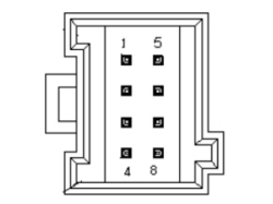
Panel Output CONNECTOR DIAGRAM
|
Connector pin out |
|
|
Pin |
Function |
|
1 |
Spare |
|
2 |
Spare |
|
3 |
Hazard |
|
4 |
|
|
5 |
Lighting |
|
6 |
Earth |
|
7 |
Unlock |
|
8 |
Lock/Unlock warning light |