|
STEP |
CHECK TO BE PERFORMED |
REMEDIAL ACTION IF THE CHECK IS NOT OK |
|
1 |
"MODE" button check Disconnect the left control panel Turn the key ON Bridge terminals 4-1 at the wiring connector with a resistance of 920 Ohm and check operation. If Ok, replace the left control panel Op. 7040A82 SWITCH UNIT ON LEFT SIDE OF DASHBOARD - R.R. Connect the multimeter at terminals 4-1 of the panel: the reading should be 920 Ohm ±1% when the Mode- button is operated |
Restore correct wiring |
|
2 |
"MODE +" button check Disconnect the left control panel Turn the key ON Bridge terminals 4-1 at the wiring connector with a resistance of 240 Ohm and check operation. If Ok, replace the left control panel Op. 7040A82 SWITCH UNIT ON LEFT SIDE OF DASHBOARD - R.R. Connect the multimeter at terminals 4-1 of the panel: the reading should be 240+25 Ohm when the Mode+ button is operated. |
Restore correct wiring |
|
3 |
"MODE-" button check Disconnect the left control panel Turn the key ON Bridge terminals 12-1 at the wiring connector and check operation. If Ok, replace the left control panel Op. 7040A82 SWITCH UNIT ON LEFT SIDE OF DASHBOARD - R.R. Connect the multimeter at terminals 12-1 of the panel: the reading should be <25 Ohm when the Mode- button is operated |
Restore correct wiring |
|
4 |
Check on fog lights button wiring Turn the key ON Bridge terminals 7-1 at the wiring connector with a resistance of 1 Ohm and check operation of fog lights. If the check is OK, replace the control panel Op. 7040A82 SWITCH UNIT ON LEFT SIDE OF DASHBOARD - R.R. Connect the multimeter at terminals 7-1 of the panel: the reading should be 1 KOhm ±1% when the fog lights button is operated |
Restore correct wiring |
|
5 |
Rear fog lamps button wiring check Turn the key ON Bridge terminals 7-1 at the wiring connector and check operation of rear fog lamps. If the check is OK, replace the control panel Op. 7040A82 SWITCH UNIT ON LEFT SIDE OF DASHBOARD - R.R. Connect the multimeter at terminals 7-1 of the panel: the reading should be <25 Ohm when the rear fog lamps control is operated |
Restore correct wiring |
|
6 |
Symbols lighting check With the side lights on, the voltage at the wiring connector should be 12 Volt between terminals 2-1 with earth at 1. If OK, replace the left control panel Op. 7040A82 SWITCH UNIT ON LEFT SIDE OF DASHBOARD - R.R. Provide the panel, at terminals 2-1, with a 12 Volt power supply and check that all the symbols light up. |
Restore correct power supply. |
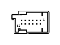
Left control panel connector
|
Connector pin out |
|
|
Pin |
Function |
|
1 |
Earth |
|
2 |
Lighting positive |
|
3 |
CAF Up-Down control |
|
4 |
MODE+ control |
|
5 |
Free |
|
6 |
Free |
|
7 |
FN-RN control |
|
8 |
Free |
|
9 |
Free |
|
10 |
Spare |
|
11 |
Spare |
|
12 |
MODE- control |