|
STEP |
CHECK TO BE PERFORMED |
REMEDIAL ACTION IF THE CHECK IS NOT OK |
|
1 |
Power supply check (+15) · With the ignition on, check for the presence of battery voltage between pin 1 of 16-way connector B of the control unit and earth · Check that the connector is correctly inserted in the other part. - Try to move it from its housing by making small movements in all directions, grasping the connector body in your fingers and the wiring in your hand. The connector should stay in place. · Exert a moderate pulling force. The connector should stay in place. · Check whether the power supply goes off, goes on and/or vice versa (touching/not touching) · Pull the lead and check the stability in the groove (it should not move back): exercise repeated pull-push-pull cycles on the lead and ensure its immobility. Crimping examination: Use a lens to examine the terminal crimping area. The barrels should be turned symmetrically and no strands should emerge from the crimped area. The bare wire section under the barrels should emerge by about 0.5 |
If blown, replace fuse F51 in the dashboard junction unit after identifying the cause Restore the wiring between the dashboard junction unit and parking sensor node. |
|
2 |
Earth check Disconnect the 16-way connector for the control unit and connect the ohmmeter between pin 8 and earth and check that the resistance is less then 1 ohm |
Restore the correct earth connection |
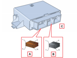
|
Parking sensor control unit pin out |
|
|
Connector A |
|
|
Pin 1 |
+12 ignition |
|
Pin 2 |
N.C. |
|
Pin 3 |
N.C. |
|
Pin 4 |
N.C. |
|
Pin 5 |
Negative signal from trailer control unit to exclude the parking sensors |
|
Pin 6 |
N.C. |
|
Pin 7 |
B CAN A |
|
Pin 8 |
Chassis earth |
|
Pin 9 |
N.C. |
|
Pin 10 |
N.C. |
|
Pin 11 |
N.C. |
|
Pin 12 |
N.C. |
|
Pin 13 |
N.C. |
|
Pin 14 |
B CAN B |
|
Pin 15 |
N.C. |
|
Pin 16 |
N.C. |
|
Connector B |
|
|
Pin 1 |
Sensor earth |
|
Pin 2 |
N.C. |
|
Pin 3 |
N.C. |
|
Pin 4 |
left outer sensor |
|
Pin 5 |
right outer sensor |
|
Pin 6 |
left inner sensor |
|
Pin 7 |
right inner sensor |
|
Pin 8 |
N.C. |
|
Pin 9 |
N.C. |
|
Pin 10 |
N.C. |
|
Pin 11 |
N.C. |
|
Pin 12 |
Sensor power supply |