|
STEP |
CHECK TO BE PERFORMED |
REMEDIAL ACTION IF THE CHECK IS NOT OK |
|
1 |
Control panel circuit continuity check Disconnect the wiring from the control panel Connect an Examiner in Ohmmeter mode between pins 1 and 2. The resistance value should read 4860 Ohms ±10% at 20°C |
Replace the control panel Op. 5580M20 ON BOARD NAVIGATION SYSTEM CONTROLS - R.R. |
|
2 |
SOS button check Disconnect the wiring from the control panel Connect an Examiner in Ohmmeter mode between pins 1 and 2 Press the SOS button. The resistance value should read 49 Ohms ±10% at 20°C |
Replace the control panel Op. 5580M20 ON BOARD NAVIGATION SYSTEM CONTROLS - R.R. |
|
3 |
NAV button check Disconnect the wiring from the control panel Connect an Examiner in Ohmmeter mode between pins 1 and 2 Press the NAV button. The resistance value should read 440 Ohms ±10% at 20°C |
Replace the control panel Op. 5580M20 ON BOARD NAVIGATION SYSTEM CONTROLS - R.R. |
|
4 |
INFOMOBILITY button check Disconnect the wiring from the control panel Connect an Examiner in Ohmmeter mode between pins 1 and 2 Press the INFOMOBILITY button. The resistance value should read 177 Ohms ±10% at 20°C |
Replace the control panel Op. 5580M20 ON BOARD NAVIGATION SYSTEM CONTROLS - R.R. |
|
5 |
Control panel power supply check Connect the wiring for the control panel Turn the ignition key to the ON position Using an Examiner in Voltmeter mode, check for a battery voltage of 12 Volts between pins 5 and 6 |
Replace fuse F49 in the dashboard junction unit after finding out what caused it to blow Restore or, if necessary, replace the electrical wiring between the control panel and the dashboard control unit. Replace the control panel Op. 5580M20 ON BOARD NAVIGATION SYSTEM CONTROLS - R.R. if the previous checks have not revealed any faults |
|
6 |
Button power supply check Connect the wiring for the control panel Turn the ignition key to the ON position Using an Examiner in Voltmeter mode, check for a voltage of around 3.5 Volts between pins 1 and 2 |
Replace the control panel Op. 5580M20 ON BOARD NAVIGATION SYSTEM CONTROLS - R.R. |
|
7 |
Voltage signal check Connect the wiring for the control panel Turn the ignition key to the ON position Using an Examiner in Voltmeter mode, check the voltage signals between pins 1 and 2 as in the table below: Press the SOS button and read a voltage of around 0.6 Volts Press the NAV button and read a voltage of around 2.2 Volts Press the INFOMOBILITY button and read a voltage of around 1.4 Volts |
Replace the control panel Op. 5580M20 ON BOARD NAVIGATION SYSTEM CONTROLS - R.R. |
|
8 |
Wiring check Check the continuity of the wiring between the control panel and the Bluetooth node |
Restore the continuity of the wiring between the control panel and the Bluetooth node. Check for any errors on the CAN If no faults have been found during the previous checks, replace the Bluetooth node |
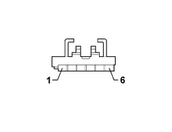
Blue & Me Nav control panel connector
|
Connector pin out |
|
|
Pin |
Function |
|
1 |
Negative signal |
|
2 |
Reference earth |
|
3 |
N.C. |
|
4 |
LED control signal |
|
5 |
Earth |
|
6 |
+12 ignition |