ALARM SYSTEM
The alarm system performs:
- perimeter surveillance,
- volumetric surveillance,
- anti-tilt surveillance,
- surveillance of supply lead cutting.
System operation is co-ordinated by the Body Computer, which sends/receives commands from external modules via the serial line.
The system is turned on/off by means of a remote control interfaced with a receiver in the NBC, the remote control unit and the receiver are radio controlled.
The doors are locked upon insertion.
To turn the alarm off completely (for example, if the vehicle is not being used for a long time) the vehicle must be closed by turning the metal insert in the key in the lock without using the remote control.
The volumetric and anti-tilt protection only can be excluded by operating a button in the front courtesy light.
Every break in attempt is signalled by the code warning light in the instrument panel coming on together with a message shown in the display.
The control unit is equipped with a self-diagnosis function which detects and memorises faults and problems in the control unit and system components; in addition, it checks the condition of the connecting cables and saves the number of activations and times the alarm has been operated.
The control unit operating logic can be modified in order to satisfy the legal requirements which govern the use of alarm systems in the various markets.
DIRECT INPUTS:
- Negative signal from switch signalling driver's door open (NO)
- Negative signal from switch signalling passenger door open (NO)
- Negative signal from switch signalling boot open (NO)
- Negative signal from switch signalling bonnet open (NC)
- Key-on power supply IN (+15)
- Serial line with volumetric/anti-tilt sensor control unit
- DIRECT OUTPUTS
- Serial line with alarm control unit and volumetric/anti-tilt sensor control unit
- Direction indicator activation
- A-bus serial line
Structure
The alarm system consists of the following modules:
- Body Computer: manages system operation and controls external modules.
- Sensors on the doors, boot and bonnet: detect attempts to open the doors, boot and bonnet.
- Remote control system (sender unit + receiver included in the Body Computer)
- Siren: emits signal beeps and an acoustic alarm.
- Ultrasound sensors: detect movements inside the passenger compartment.
- Anti-tilt sensor: detects a change in vehicle tilt following lifting.
- A-bus serial line: connects all relevant modules to the alarm system.
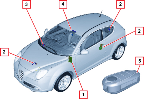
1 - Body Computer
2 - Switches on doors
3 - Siren
4 - Ultrasound/anti-tilt sensors
5 - Remote control
Operation
There are eight different possible statuses for the alarm system:
- DEACTIVATED;
- REST;
- ON;
- SURVEILLANCE;
- ALARM;
- OFF;
- PROGRAMMING;
- FAULT DIAGNOSIS.
Each of these statuses is described in the following paragraphs.
Deactivated
The deactivated status is the status the Body Computer is in each time a key enabled by the ALFA ROMEO CODE is recognized.
This operation effectively turns off the alarm.
When the alarm system is deactivated it does not respond to the commands from the receiver (key on).
It changes from deactivated to rest status when the key is removed.
Rest
Rest status is the basic alarm system status.
It is possible to change from rest status to the following statuses:
- fault diagnosis: when a diagnosis session is activated by means of a diagnosis instrument connected to the Body Computer.
- surveillance: when the vehicle is protected by issuing an on command and passing through the on stage.
- deactivated: when the ALFA ROMEO CODE recognizes an enabled key.
In the rest condition, the BC continues to acquire the +15 status to prevent a switch to surveillance and, especially, alarm.
This information distinguishes two fundamental rest modes: vehicle operating (+15 present) or abandoned (+15 absent) which introduces the surveillance condition.

|
During rest status, it is possible to cut out volumetric and anti-tilt protection manually within one minute of KEY OFF. |
On
The on command changes the alarm from rest to surveillance mode
This operation is always inhibited in the presence of the +15 signal.
The on command takes place by pressing the sender unit button and is signalled by the direction indicators coming on for 2.5 secs and a beep.
When the command is received, the BC activates the alarm activation procedure as described within 100 ms:
SIGNALLING OF SWITCHING ON IN PROGRESS:
- Blinkers activated with fixed light for 1 s.
- LED in central locking button on constantly for 1 sec.
- BEEP command sent to siren.
SYSTEM DIAGNOSIS/VERIFICATION:
The control unit diagnoses the following components:
- volumetric/tilt sensor modules;
- siren;
It verifies sensor status via appropriate commands:
- after max. 3 seconds, the siren;
- after max. 3 seconds, the siren;
- after max. 4 seconds, the volumetric sensor module;
- after max. 4 seconds, the anti-tilt module.
|
|
If the responses to the verification commands are not received within the required times, the module is declared non-operational. |
Plausibility of door (2 or 4), bonnet and boot switch statuses is also checked (perimeter protection): If one of the entrances if found not to be closed, this entrance is excluded from surveillance.
DIAGNOSIS INFORMATION DISPLAY:
The signalling of problems when switching on is carried out by the warning light in the control panel which is only supplied at the next Key On.
Automatic activation
|
|
The automatic activation function can only be activated in certain markets. |
Automatic activation allows the alarm system to switch from rest to surveillance mode in an automatic, timed manner.
Two self-activation modes are provided.
FROM KEY-OFF:
- KEY OFF is detected;
- The self-activation counter begins counting;
- If a closed/open transition is detected at any door or the bonnet or the boot then the counter begins from zero;.
- The counter reaches the "SELF-ACTIVATION TIME" value.
- The BC checks whether an enabled key is inserted;
- If an enabled key is inserted, self-activation takes place;
- If no enabled key is present, self-activation does not take place.
PASSIVE mode (last door):
- KEY OFF is detected;
- The self-activation counter begins counting;
- If a closed/open transition is detected at the driver's door, on any of the doors or the bonnet or the boot then the counter begins from zero;.
- if the counter reaches 2 minutes without any open to closed transition being recorded, self-activation is cancelled;
- the counter reaches the "SELF-ACTIVATION TIME" value;
- the BC checks whether an enabled key is inserted;
- if an enabled key is inserted, self-activation takes place;
- if no enabled key is present, self-activation takes place;
Self-activation modes are enabled according to the operating mode (see country map table "PASSIVE SELF-ACTIVATION ENABLING" and "KEY-OFF SELF-ACTIVATION ENABLING").
Surveillance from self-activation is complete for all entrances. The operating modes allow:
- activation/deactivation of volumetric surveillance.
- activation/deactivation of the tilt module.
The central locking is not activated during the self-activation stage.
Warning lights/acoustic signals are enabled by the operating mode.
The definition of the driver's side door for different specifications (right hand drive and left hand drive) is specified during the manufacturer's end of line programming.
Reactivation
The reactivation operation allows the system to move automatically from the REST stage to the SURVEILLANCE stage when, after an authorized deactivation, door/boot/bonnet opening or other consistent actions are not found to have occurred.
The procedure for reactivation is as follows:
- The alarm system is switched off.
- The reactivation counter begins counting.
- If a closed/open transition is detected at any of the doors or the bonnet or the boot then reactivation is cancelled.
- The counter reaches the "SELF-ACTIVATION TIME" value.
- The alarm is switched on taking into account any system exclusions (volumetric protection, siren,...) made at the last switching on.
Surveillance
During the surveillance status, the BC performs the following operations:
- +15 SIGNAL CHECK
The BC acquires information on the presence of the +15: if it detects the presence of the +15 signal for longer than 100 ms without a prior switching off command, the BC interprets this manoeuvre as a theft attempt and commands a switch to the alarm status.
- EXCLUSION OF EXTERNAL MODULES DUE TO LOW BATTERY VOLTAGE
If the battery voltage is below 8.5 V for longer than 30 minutes, the BC deactivates the external modules (volumetric sensors, tilt sensor) in order to safeguard the life of the battery and to be able to start up the engine later on.
- PERIMETER SURVEILLANCE
The BC monitors the status of the six inputs from the four doors, bonnet and boot: if one of these changes status for longer than 500 ms, the BC changes to alarm status.
- PROTECTION AGAINST FALSE ALARMS DUE TO BC RESET
During the surveillance stage, external interference or a theft attempt could cause the BC to reset and re-initialize its functions.
In this case, the BC checks whether the alarm was on before the reset so it can re-activate the external modules, except for those excluded at the last activation.
- ALARM ACTIVATION
During the surveillance stage, the alarm may be activated by the perimeter protection and also by the external modules or the siren (due to the wires being cut).
When one of the alarm activation signals is received, the BC immediately changes to alarm status and triggers the cycle specified for the type of alarm received.
Alarm
If one of the sensors involved in the surveillance identifies an irregular situation (attempted or actual intrusion, interference and/or theft of the vehicle), the alarm system moves to ALARM status.
Alarm status is characterised by the activation of optical/acoustic signals consisting of activation of the siren and indicators.
SIGNALS
The signalling consists of a succession of alarm cycles.
Operating mode parameters are defined in the "operating mode" table.
The type, number and duration of alarm cycles for each mode are managed by the BC: the siren may only be turned on (sound emission starts) and off (sound emission ceases).
For example, if the operating mode requires the emission of 3 alarm cycles lasting 26 seconds at 6 second intervals, the BC will behave as follows:
- Blinker activation and control of siren activation with associated sound configuration parameters.
- After 26 seconds of blinker deactivation, the siren is deactivated.
- 6-second wait.
- Repetition of previous points until the cycles are exhausted.
STORING THE ALARM CAUSE
For diagnosis purposes, a record of the alarm causes recognised by the BC is kept.
The NBC memorizes the last 10 alarm causes, associating the cause and alarm system statuses at the time the system was switched on with each of the causes.
The following alarm causes can be memorized:
- driver's side door
- passenger's side door
- ultrasound sensor
- anti-tilt sensor
- cutting of siren cables
- boot
- bonnet
- +15
- +30 cable cutting
- siren intrusion with incorrect siren deactivation command
- intrusion on external modules with ultrasound/anti-tilt deactivation command
- incorrect heart-beat
For each alarm cause, the system status is memorized, described by:
- left door open
- right door open
- bonnet open
- boot open
- system activated by self-activation
- system activated by remote control
- ultrasound sensor defective
- anti-tilt sensor defective
- siren defective
- serial line not operational
The system changes from alarm status to the following statuses:
- rest: through a switching off command or through the recognition, at Key On, by the ALFA ROMEO CODE of an enabled key.
- surveillance: when the alarm cycles set off are ended.
Deactivation
Deactivation may occur in surveillance mode or in alarm mode.
This is carried out by pressing the key on the sender unit, which commands the BC to deactivate the alarm system according to the following procedure: deactivation is indicated by two flashes of the 1 Hz blinkers and two synchronous beeps (indication is enabled/not enabled according to the operating mode).
This signal is activated within 100 ms of receiving the deactivation command:
- the siren is deactivated.
- external modules are deactivated.
- the BC interrupts the perimeter protection and, if present, all counter-measures activated.
The command is also accepted if the +15 signal is present.
After deactivating and at the first key on, the control unit runs the signals for sender unit batteries flat, alarms from volumetric, tilt and perimeter sensors, +15 and +30.
End of line programming
It is possible to programme the configuration of the alarm system installed on the vehicle at the end of line by defining the presence/absence of the following modules:
- siren;
- ultrasound module;
- tilt module.
This information can be read, but not modified, by the diagnosis instrument which will adapt its diagnosis procedures depending on the configuration present.
The configuration is transferred to the Body Computer by means of the vehicle "Customisation" procedure (PROXI).
Programming operating modes
The programming status allows the BC to store the active operating mode in its EEPROM.
It allows the alarm system to be configured so that it acts in accordance with legal requirements expressed in the "operating mode" table.
During programming, the system changes to rest status.
Operating modes
A list of the different operating modes is given below:
MODE 1 DEFAULT MODE (EEC)
MODE 2 (Great Britain)
MODE 3 (Belgium)
MODE 4 (Holland)
MODE 5 (World)
MODE 6 (Temporary market)
Operating mode table
|
FUNCTION |
1 |
2 |
3 |
4 |
5 |
6 |
7 |
|
COUNTRY |
EEC |
G.B. |
BELGIUM |
HOLLAND |
WORLD |
TEMP |
RANGE |
|
ALARM SELF RESET FOR EACH MONITORED INPUT |
YES |
YES |
YES |
YES |
YES |
X |
N/A |
|
PASSIVE SELF-ACTIVATION ENABLING |
NO |
NO |
YES |
NO |
NO |
X |
N/A |
|
SELF-ACTIVATION AT KEY OFF ENABLING |
NO |
NO |
NO |
NO |
NO |
X |
N/A |
|
REACTIVATION ENABLING |
NO |
NO |
NO |
NO |
NO |
X |
N/A |
|
AUTOMATIC ACTIVATION FROM LAST DOOR OPENING/CLOSURE |
YES |
YES |
YES |
YES |
YES |
X |
N/A |
|
AUTOMATIC ACTIVATION FROM DRIVER'S DOOR OPENING/CLOSURE |
NO |
NO |
NO |
NO |
NO |
X |
N/A |
|
ALARM SELF-ACTIVATION WITH TRANSPONDER RECOGNIZED AND ENABLED |
NO |
NO |
NO |
NO |
NO |
X |
N/A |
|
SELF-ACTIVATION TIME (S) |
28 |
28 |
28 |
28 |
28 |
X |
120 |
|
TILT MODULE SURVEILLANCE DURING AUTOMATIC ACTIVATION |
YES |
YES |
YES |
YES |
YES |
X |
N/A |
|
VOLUMETRIC SURVEILLANCE DURING SELF-ACTIVATION |
YES |
YES |
YES |
YES |
YES |
X |
N/A |
It is possible to change the market from 1, 2, 3, 4, 5 using the diagnosis instrument or a manual procedure.
It is not possible to enable/disable the market by entering 0.
External modules fault diagnosis
The BC diagnoses the operation of the serial line for connection to the siren and external modules, checking for short circuits to earth, to the battery and for the presence of open circuits.
A diagnosis check is carried out on the serial line when communication is activated, typically upon activation of the alarm system.
The external modules are diagnosed when the system is activated by diagnosis commands from which the following information is obtained.
No diagnosis checks are required for the perimeter protection switches.
The diagnosis information obtained at the time of activation is stored in the EEPROM to ensure the system can be serviced.
To carry out the fault diagnosis, use the diagnosis instrument provided.
Active diagnosis
During a diagnosis session, the BC may be required to carry out a diagnosis check on the external modules: the BC then sends the appropriate command and communicates the outcome to the diagnosis instrument.
If the BC cannot communicate with the module during this operation, the response to the diagnosis instrument will be:
- serial line interference
- module not responding.
Similarly, a diagnosis check may be requested on the serial line, with the following possible outcomes.OK, short circuit to earth, short circuit to battery.
It is also possible to read the alarm cause table stored in the BC.
Recovery
If an external module (ultrasound, tilt) is recognized as not functioning, it is excluded for the entire surveillance cycle.
The next time the system is switched on, the diagnosis check is carried out again on the modules which should be reactivated if they are recognized as working.
Components
Anti-theft device siren
The following figure shows the anti-theft siren.
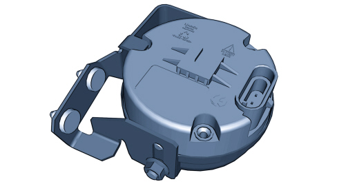
The main specifications of the siren are:
- sealed casing;
- green batteries for self-powering once the cables have been cut;
- battery recharging from control;
- programmable acoustic emission type;
- serial communication with the Body Computer and other anti-theft system components;
- self-diagnosis.
The siren (Stand –alone) is connected to the rest of the system with:
- a dedicated serial line between the Body Computer and siren;
- power supply for the siren/internal battery recharging.
The siren can respond to diagnosis messages sent by the Body Computer (internal self-diagnosis).
The siren is located in the engine compartment, in the housing under the windscreen.
SIREN PIN OUT
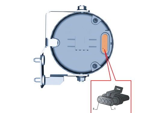
1 - Siren power supply
2 - Serial line
3 - Earth
4 - N.C.
Volumetric / tilt sensors
The volumetric and anti-tilt sensors are located inside the courtesy light.
The volumetric sensors consist of a receiver and an ultrasound receiver fitted in a module connected to the anti-theft control unit.
The tilt sensor detects angular changes compared to the vehicle longitudinal axis and transverse axis.
Both sensors may be deactivated (together and not separately) by means of the appropriate button.
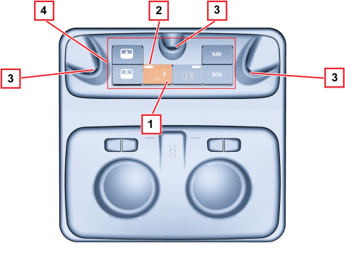
1 - Sensor deactivation button
2 - Sensor deactivation LED
3 - Ultrasound volumetric sensors
4 - Tilt sensor (inside courtesy light)
Receiver
The remote control/receiver system interfaces with the Body Computer to activate the following functions:
- activate the central opening and closing of the doors and, in some cases, the windows,
- turn the alarm system on and off.
The remote control system consists of:
- transmitter: incorporated in the key: radiofrequency, it sends a rolling code to the receiver. It has three function control keys and a LED to verify code transmission and battery charge status.
- receiver: radio-controlled, built into the Body Computer with an operating frequency of 433.92 Mhz.
The receiver is located in the Body Computer and is equipped with a wire aerial that emerges from the Body Computer.
The receiver module has the following functions:
- to receive and decode signals from the sender unit;
- store up to 8 transmitters;
- generate a door opening and closure command (by exiting blinker control, if required);
- turn the anti-theft system on and off;
The remote control and receiver system has two operating modes:
- on;
- off.
ON CONTROL
At the on control, the receiver sends a signal to the Body Computer, which:
- implements door locking
- controls a change in anti-theft system status from rest to surveillance if the BC is designed to do this.
The on command is issued by pressing a key button on the sender unit: it is indicated by the direction indicators coming on for 2.5 s (the signal is enabled/disabled via the EEPROM).
Engagement is always inhibited (except during fault diagnosis) in the presence of the +15 key-on signal.
When the button is pressed, the sender unit LED flashing frequency is 3 Hz.
The sender unit transmits the full rolling code in response to continuous pressure on the button lasting at least 50 ms.
If the button is held down continuously, the sender unit interrupts transmission after 20 seconds.To continue transmitting, release the button on the sender unit and press again.
If the receiver detects a continuous transmission (code received always the same), after the first status switch, it excludes the possibility of continuous command switching.
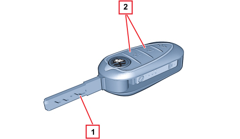
1 - Mechanical key
2 - Door locking/unlocking buttons, alarm activation/deactivation
ON
The receiver acquires the rolling code, compares it with codes stored during the programming stage and identifies it from among them.
Once the code has been recognized, the receiver locks the doors and changes the alarm from rest to surveillance mode if the BC is designed to do this.
If the BC contains an anti-theft system, if the vehicle has been locked beforehand using a mechanical key, the BC must implement the door lock/alarm activation as indicated below when the sender unit button is activated:
- doors locked with key and alarm off (self-activation time not yet elapsed): no door lock operation and alarm activation;
- doors locked with key and alarm on (self-activation time already elapsed): operation of door lock (opening) and alarm deactivation;
- doors unlocked and alarm off (self-activation time not yet elapsed): operation of door lock (locking) and alarm activation;
- doors unlocked and alarm on (self-activation time already elapsed): no door lock operation and alarm deactivation.
DEACTIVATION
Once the receiver has received an off command from the sender unit, it sends a message to the Body Computer which:
- controls the unlocking of the doors.
- allows a change in the alarm system status from surveillance to rest if the BC is designed to do this.
The system is turned off by pressing the button in the sender unit: the signal is issued by two flashes of the blinkers at 1 Hz, d.c. 50% (function enabled/disabled via the EEPROM).
The deactivation is also enabled if the +15 signal is present.
The receiver controls the unlocking according to the rules described in the activation paragraph (only if lock status is active).
Alarm system deactivation is also controlled.