INTRODUCTION
The "Parking Assistance" system supplies the driver with information on distance when approaching obstacles behind the vehicle thereby providing help with parking manoeuvres and identifying obstacles that are outside the field of vision.
The driver is notified of the presence and distance of the obstacle from the vehicle by an acoustic signal which varies depending on the distance from the obstacle (as the distance from the obstacle decreases the frequency of the acoustic signal increases).
Display on instrument panel (MATRIX display only)
The following appears when the rear obstacles are activated while parking:
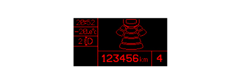
The concerned sectors light up in proximity of obstacles. There are 8 sectors in total.
The distance measurement only takes place when the system is activated, whilst only the control unit is operational in the inactive state.
The parking assistance system comprises the following components:
- electronic control unit
- ultrasound sensors located in the rear bumper
- buzzer built into the instrument panel
The electronic control unit activates and controls the operation of the sensors located in the rear bumper, processes the signals received and operates the buzzer in the instrument panel.
REAR SENSORS:
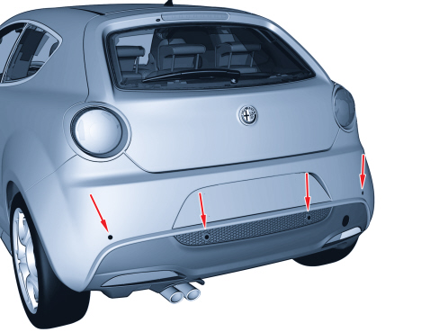
OPERATION
Activation and deactivation of the system
The system is activated if the following conditions are present simultaneously:
- key ON
- reverse gear engaged
When the system is activated, the buzzer sounds and the display is activated.
Obstacle distance acoustic signals
The control unit processes information supplied by sensors, operating the two dedicated buzzers (or the one incorporated in the instrument panel) to signal the presence of any obstacles.
The sound from the buzzer warns the driver that the vehicle is approaching an obstacle. The sound lasts for 75 ms, whilst the pause between the sounds is directly proportional to the distance of the obstacle: impulses in quick succession indicate the presence of an obstacle that is very close. A continuous sound indicates that the obstacle is less than 30 cm away.
The acoustic signal stops immediately if the distance of the obstacle increases. The sound cycle remains constant if the distance measured by the centre sensors remains unchanged, whilst if this situation occurs for the side sensors, the signal is interrupted after 3 seconds (for example, to prevent signals in the case of manoeuvres alongside walls).
Measuring distance of obstacles
The electronic control unit controls the sensors, which convert the control unit electrical signals into ultrasound impulses at a rhythm which varies between 3 and 10 measuring processes per second.
The signal, reflected by any obstacles, is received by the sensor and amplified by it, converted into a digital signal and sent, in this format, to the electronic control unit.
The control unit compares the signal transmitted with the one received and, using suitable algorithms, calculates the time elapsed between the issue of the signal and the reception of the echo. This information is translated into distance and the driver is notified by means of acoustic signals.
As the vehicle moves towards an obstacle, the "first approach distance" is defined as the distance at which the system starts to produce the initial intermittent signals and later on the "second approach distance" is defined as the distance at which the signal becomes constant.
The distances are measured along the perpendicular to the bumper passing through the point involved.
The reference obstacle is a pipe 100 centimetres high and 7.5 centimetres in diameter (ISO obstacle).
The "first approach distance" should be a minimum value of around 150 centimetres from the edge of the vehicle and along the entire rear width (except for the rear view mirrors). The second approach distance should be between 20 and 30 centimetres from the edge of the vehicle and along the entire rear width (except for the rear view mirrors). The first approach distance for non-aligned obstacles in relation to the side of the vehicle should be about 60 centimetres.
The minimum height of an obstacle that can be detected corresponds to the maximum height of an obstacle which does not impact the vehicle during a parking manoeuvre.
Reflections from the ground are ignored unless they have the characteristcs of an obstacle.
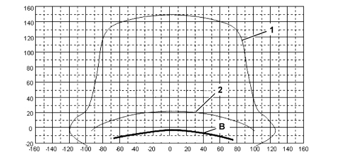
1 - first approach distance
2 - second approach distance
B - bumper
Auto diagnosis and recovery
The control unit carries out an auto diagnostic test when it is turned on. The sensors are diagnosed every time they are activated. A fault even in only one sensor inhibits the operation of the entire system which is deactivated.
Any faults/errors are signalled in the instrument panel by the relevant warning light coming on and the message "PARKING ASSISTANCE NOT AVAILABLE" in the display.
Presence of trailer
If there is a trailer, rear obstacles are not signalled thanks to a dedicated connection between the control unit and a socket in the tow hook.
This connection is made in the aftermarket when the tow hook is fitted.
COMPONENT SPECIFICATIONS
Parking sensor control unit
The control unit is an electronic component connected to the rear wiring that manages the assistance function by carrying out the following functions:
- receiving signals via the CAN (+15, reverse, etc.)
- activating the sensors
- processing the signals received by the sensors
- checking the operation of the sensors
- operating the buzzers
- managing the fault diagnosis and test functions
The electronic control unit has a device that protects against voltage fluctuations and short circuits.
It is located in the passenger compartment, under the rear seat; it is connected by three connectors:
- CONNECTOR A: control unit power supply and signals from other nodes or vehicle components;
- CONNECTOR B: rear bumper sensors connection;
- CONNECTOR C: not connected.
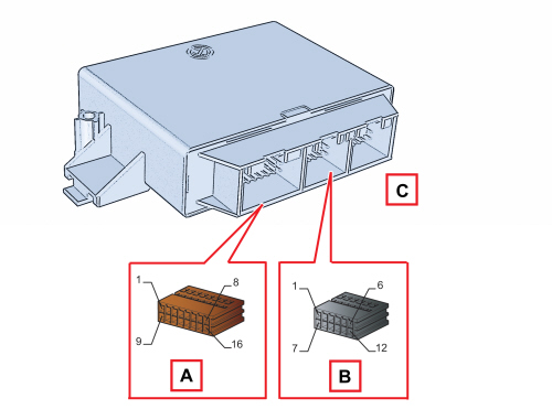
Control unit pin out
CONNECTOR A
|
Pin |
Signal |
|
1 |
+ignition power supply from F51 |
|
2 |
Rear parking system buzzer negative (N.C.) |
|
3 |
not connected |
|
4 |
Negative signal from front parking system deactivation control (N.C.) |
|
5 |
Signal from trailer control unit (connection to be made in the after market) |
|
6 |
C CAN (high) (N.C.) |
|
7 |
B CAN A (low) |
|
8 |
Chassis earth |
|
9 |
Parking system activation/deactivation signal warning light positive command (N.C.) |
|
10 |
Rear parking system buzzer positive (N.C.) |
|
11 |
Not connected |
|
12 |
K line (N.C.) |
|
13 |
Parking system deactivation signal warning light positive command (N.C.) |
|
14 |
B CAN B (high) |
|
15 |
C CAN (low) (N.C.) |
|
16 |
Negative signal from parking system activation/deactivation control (N.C.) |
CONNECTOR B
|
Pin |
Signal |
|
1 |
Reference earth from auxiliary parking control unit for sensors on rear bumper |
|
2 |
Not connected |
|
3 |
Not connected |
|
4 |
Signal from sensor on left outer rear bumper |
|
5 |
Signal from sensor on right outer rear bumper |
|
6 |
Signal from sensor on left inner rear bumper |
|
7 |
Signal from sensor on right inner rear bumper |
|
8 |
Not connected |
|
9 |
Not connected |
|
10 |
Not connected |
|
11 |
Not connected |
|
12 |
Power supply for sensors on rear bumper from parking control unit |
Ultrasound sensors
The sensor is an ultrasound transducer which acts as an intelligent transmitter and receiver of ultrasound impulse packages. Both the frequency and the voltage of the impulses are produced in the transducer.
The impulses emitted are reflected by any obstacles; the transducer therefore receives an echo which is amplified and converted into a digital signal, sent to the electronic control unit via the same line used for the transmission request.
Each sensor can also be operated as a receiver only, in order to be able to take a triangular measurement between two sensors.
This technique allows better detection both of small obstacles and in situations featuring critical reflection.
The sensors all have the same electrical and mechanical properties; the maximum detection distance for each sensor can be adjusted using software according to the location of the actual sensor.
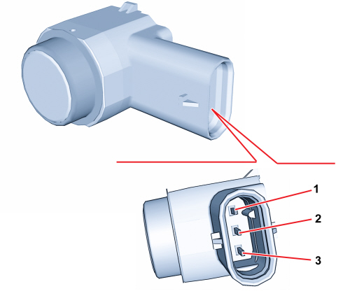
Sensor pin out
|
Pin |
Signal |
|
1 |
Sensor power supply |
|
2 |
Sensor signal |
|
3 |
Sensor earth |