PASSIVE SAFETY SYSTEM
The vehicle is equipped with an electronic control system that governs the activation of specific containment devices in the event of front or side impact:
The front protection system includes:
- dual activation stage driver's front Air Bag;
- dual activation stage passenger front Air Bag;
- driver's knee bag;
- front seat belts with dual pretensioner and load limiter;
- rear seat belts with load limiter;
- additional frontal impact detection sensor;
The side protection system consists of:
- two side bags housed in the front seats;
- two window bags housed in the side members under the roof;
- two impact detection sensors located in the central pillar.
The front air bag - driver and passenger - adopts a dual stage module which is capable of automatically adapting the activation parameters depending on the seriousness of the impact:
- when the impact is of moderate severity, the electronic control unit controls the first air bag activation stage so that the energy discharged onto the occupant is not harmful;
- for very severe crashes, the control unit activates the first and second stage with a very slight delay in order to absorb the occupant's greater kinetic energy before they strike the steering wheel.
- for medium severity impacts the second stage is also activated after a preset time to ensure the charge is used fully.
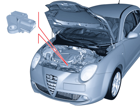
- an early crash sensor, located on the front crossmeber near the bonnet lock, helps the electronic control unit to anticipate the intervention of all the front air bags.

|
the system components have been specifically designed to work on a specific vehicle. For this reason THEY CANNOT be tampered with, adapted or installed on other types of vehicle. |
|
|
For safety reasons, NO continuity checks can be carried out on the wiring. |
The electrical connection between the air bag system components is via dedicated wiring built into the dashboard cable loom and the rear cable loom.
The connection between the control unit and the system is achieved via two connectors, one for the dashboard cable and one for the rear cable.
The control unit is connected to the vehicle CAN through which it exchanges information with the other nodes, turns on the instrument panel warning lights and carries out diagnostic operations.
Because the control unit is a node in the CAN, the air bag system is connected:
- to the standard diagnostic socket via the CAN
- to the instrument panel, again via the CAN, to control the air bag system failure, seat belt not fastened and passenger air bag deactivated warning lights in addition to the belt not fastened buzzer.
- to the Body Computer for potential end of line customisation (Proxy) with a consequent reduction in the number of spare parts.
|
|
SEVERE DANGER! The front airbag module MUST be deactivated if a child seat is fitted to the front passenger seat. THIS MAY BE DISABLED BY MEANS OF THE CONTROL PANEL SETUP FUNCTION AND NOT BY USING THE KEY. When it is deactivated the warning light in the instrument panel comes on. |

|
If the vehicle is equipped with side bags, deactivation of the front passenger side air bag module also disables the side bag. |
COMPOSITION
The system consists of the following devices:
- an electronic control unit;
- driver and passenger front air bags with dual-stage activation;
- a driver's knee bag with single-stage activation;
- a supplementary impact detection sensor, the ECS (Early Crash Sensor);
- two Side Bags on the front seats;
- two window bag modules for the side protection of occupants;
- two side impact sensors in the side pillars;
- two electronic pretensionsers located on the front seat belt reels.
- two electronic pretensionsers located on the front seat belt third point mounting.
The system also provides the following to indicate the efficiency status:
- system fault warning light in the instrument panel;
- passenger air bag disabled warning light in the instrument panel;
- front seat belt not fastened warning light in the instrument panel;
- seat belt fastened reminder (front and rear);
- connection via the B-CAN with the diagnostic socket - for function checks using an EXAMINER.
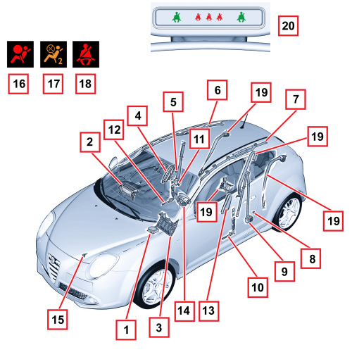
1 - Electronic control unit
2 - Passenger Air Bag module
3 - Driver's knee bag module
4 - Passenger Side Bag module
5 - Passenger side impact sensor
6 - Passenger window bag module
7 - Driver's window bag module
8 - Driver's side impact sensor
9 - Driver's reel pretensioner
10 - Driver's 3 point mounting pretensioner
11 - Passenger side reel pretensioner
12 - Passenger side 3 point mounting pretensioner
13 - Driver's side bag module
14 - Driver's air bag module
15 - Frontal impact sensor
16 - Air Bag system fault indication warning light
17 - Passenger side air bag deactivation warning light
18 - Seat belt not fastened warning light
19 - Rear belts
20 - Seat belts fastened reminder
ELECTRONIC CONTROL UNIT
The following diagram shows the control unit.
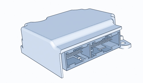
The control unit is the central occupant protection processing unit and is fastened securely to the vehicle floor pan near the central tunnel. It manages all the containment system detection and activation devices by processing signals from the various sensors distributed throughout the vehicle and internal sensors.
|
|
The control unit should always be fitted with the arrow, stamped on the adhesive plate, facing the direction of travel of the vehicle. Always check that there are no foreign bodies between the control unit and the body and tighten the bolts to the recommended torque. |
|
|
If the control unit falls to the ground or is subject to abnormal knocks during handling, it MUST be replaced. |
Composition
The control unit has an electronic deceleration sensor which, with the assistance of front and side satellite sensors and, via a dedicated calculation algorithm, manages the activation of the front and side modules and the pretensioners.
Operation
Frontal impact:
When the impact is of moderate severity, the electronic control unit controls the first air bag activation stage so that the energy discharged onto the occupant is not harmful.
Conversely, in the case of very severe impact, the control unit activates both stages almost simultaneously to absorb most of the kinetic energy from the occupant's body before it strikes the steering wheel or dashboard.
Side impact:
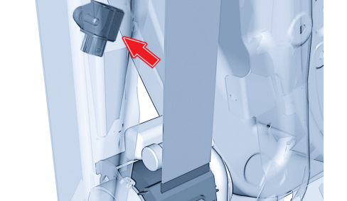
Similarly, when there is a side impact, the control unit is capable of recognizing the direction and intensity, activating the side bags and the pretensioners on the side affected by the impact. To provide total cover against side impacts, two satellite sensors located in the centre pillars are used.
When there is a side impact, the satellite sensors detect the deceleration due to the impact and notify the control unit which, by means of a dedicated calculation algorithm, manages the activation of the side modules and the pretensioners.
The side air bags (window bags and side bags) are activated simultaneously and independently of the front safety devices.
After each activation of one of the controlled systems (pretensioners, front air bags, side bags), the control unit stores the activation in its permanent memory and controls activation of the fault warning light on the instrument panel.
Before it is replaced, the control unit guarantees activation of individual devices within the following limits:
-3 impacts with activation of the seat belt pretensioners alone;
- 3 impacts in total (right or left) with side bag activation;
- 1 impact with activation of the pretensioners and front air bags;
- any combination of the above cases up to the maximum number.
If one of the limits described is not reached, it will be possible to reuse the control unit after carrying out the RESET procedure using the EXAMINER once system operating conditions have been restored. The final activation, corresponding to the maximum number for the limits indicated above, will prevent further reset procedures.
Control unit pin out
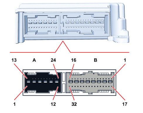
CONNECTOR A (dashboard wiring, BLACK)
|
PIN |
SIGNAL |
|
1 |
Earth |
|
2 |
+ignition power supply from F50 |
|
3 |
NC |
|
4 |
NC |
|
5 |
NC |
|
6 |
NC |
|
7 |
B-CAN A line (low) |
|
8 |
B-CAN B line (high) |
|
9 |
NC |
|
10 |
NC |
|
11 |
Frontal impact sensor (-) |
|
12 |
Frontal impact sensor (+) |
|
13 |
Passenger air bag - first stage (-) |
|
14 |
Passenger air bag - first stage (+) |
|
15 |
Driver's air bag - first stage (+) |
|
16 |
Driver's air bag - first stage (-) |
|
17 |
Passenger air bag - second stage (-) |
|
18 |
Passenger air bag - second stage (+) |
|
19 |
Driver's air bag - second stage (+) |
|
20 |
Driver's air bag - second stage (-) |
|
21 |
NC |
|
22 |
NC |
|
23 |
Driver's knee bag (+) |
|
24 |
Driver's knee bag (-) |
CONNECTOR B (rear wiring, GREY)
|
PIN |
SIGNAL |
|
1 |
Passenger side window bag (+) |
|
2 |
Passenger side window bag (-) |
|
3 |
Driver's window bag (-) |
|
4 |
Driver 's window bag (+) |
|
5 |
NC |
|
6 |
NC |
|
7 |
NC |
|
8 |
NC |
|
9 |
Passenger side bag (+) |
|
10 |
Passenger side bag (-) |
|
11 |
Driver's side bag (-) |
|
12 |
Driver's side bag (+) |
|
13 |
Front passenger belt reel pretensioner (+) |
|
14 |
Front passenger belt reel pretensioner (-) |
|
15 |
Driver's front belt reel pretensioner (-) |
|
16 |
Driver's front belt reel pretensioner (+) |
|
17 |
NC |
|
18 |
Front passenger belt 3 point mounting pretensioner (+) |
|
19 |
Front passenger belt 3 point mounting pretensioner (-) |
|
20 |
Driver's front belt 3 point mounting pretensioner (-) |
|
21 |
Driver's front belt 3 point mounting pretensioner (+) |
|
22 |
Passenger side impact sensor (+) |
|
23 |
Passenger side impact sensor (-) |
|
24 |
Driver's side impact sensor (-) |
|
25 |
Driver's side impact sensor (+) |
|
26 |
Passenger side front seat belt switch and PPD (+) |
|
27 |
Front seat belt switches (-) |
|
28 |
Driver's side front seat belt switch (+) |
|
29 |
Right rear seat belt switch (+) |
|
30 |
Central rear seat belt switch (+) |
|
31 |
Rear seat belt switch (-) |
|
32 |
Left rear seat belt switch (+) |
Self-diagnosis
The control unit carries out continuous self-diagnosis of system operation. Specifically:
- it detects and stores faults;
- it diagnoses the connections with the system components and the possible type of fault;
- it signals the onset of these faults by turning on the warning light in the instrument panel.
The faults memorised in the control unit can only be deleted after the fault has been repaired using the EXAMINER diagnosis equipment.
DRIVER'S AIR BAG MODULE
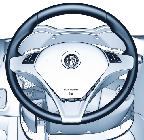
Specifications
The driver's air bag is a passive safety device.It takes the form of a bag that inflates automatically in the case of frontal impact placing itself between the driver's body and front passenger compartment structures. The air bag module is installed in the middle of the steering wheel.The module cover also acts as a horn control.
Composition
The module comprises:
- a plastic cover that tears at preset points when activated to allow the bag to expand correctly;
- a 60 litre bag, made out of nylon thread woven to minimise skin abrasions in the event of contact and folded in such a way as to ensure that inflation is gradual and not directed toward the driver;
- a pyrotechnic type gas generator;
- a plastic housing;
- the control device from the horns.
Operation
The Bag is inflated by a gas generator with two operation stages that can be activated separately according to the severity of the impact.
The gas generator is activated by two electrical resistances that burn propellant inside the generator to allow the bag to expand.
When fully inflated, the bag is in an optimum position to protect the occupant. The bag deflates immediately thanks to two openings in the lower part of the bag. These openings also serve to “soften” the passenger’s impact against the bag and prevent abrasions.
CLOCK SPRING
The clock spring is illustrated in the diagram.
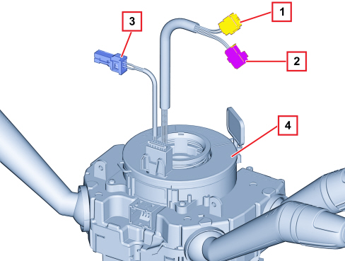
1 - Electrical connection for connecting air bag first stage
2 - Electrical connection for connecting air bag second stage
3 - Steering wheel electric functions connection (horns and radio controls)
4 - Clock spring
Specifications
The clock spring transfers the electrical signal to controls on the steering wheel (horn and other optional controls) and connects the air bag module without risk of breakage.
The device consists of two plates and is secured to the steering wheel interface via its lower plate.It is built into the steering wheel by means of fasteners on the upper plate. Inside the two plates, the leads connecting the module and horn buttons are wound in a coil so that they can follow steering wheel movements.
Composition
The clock spring is fitted with three leads on the steering wheel side.Two of these are used to connect the air bag module (first and second stage) and one to connect the steering wheel electrical functions (horn, radio controls).
A ring on the upper plate, steering wheel side, automatically prevents the two plates turning in relation to one another when the device is detached from the steering wheel.New devices are fitted with a safety key for transport, to be removed after installation.
Operation
The connecting cables for the air bag module and the various electrical functions are wound inside the two plates so that they can follow the rotation of the steering wheel.
The rotation of the upper plate is activated by means of the fasteners inside the lock ring which engage in the seat on the steering wheel hub. In a working position, the steering wheel presses on the ring to release it from its fasteners and thus allow both plates to turn freely.
When the steering wheel is removed the ring, thrust by a spring, stops the rotation between the two plates. This function prevents the upper plate, now no longer secured to the steering wheel, from turning freely and unwinding or winding the coil inside the device and possibly causing it to break.
In operations that require the removal of the steering wheel and the device it is compulsory to observe the following:
- always work with the car's wheels aligned straight ahead;
- secure both plates with a band, for safety, before removing the device from the steering wheel interface.
If the clock spring is being reused, it is advisable to secure the two shims with a band to prevent accidental rotation.
|
|
If the upper plate should turn in relation to the lower plate for any reason so that the exact starting position is no longer certain, the clock spring MUST be replaced. |
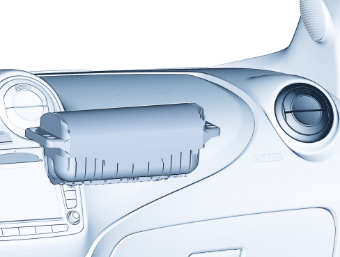
PASSENGER-SIDE AIR BAG MODULE
Specifications
The passenger air bag module is a passive safety device that protects the front passenger in the event of frontal impact by means of a bag that places itself between the occupant and the vehicle dashboard.
Composition
The module comprises:
- a plastic housing;
- a 120 litre nylon bag, a fabric that minimises skin abrasions in the event of contact. The bag is folded so that it does not inflate directly towards the occupant;
- a pyrotechnic type gas generator.
Operation
The Bag is inflated by a gas generator with two operation stages that can be activated separately according to the severity of the impact.
The gas generator is activated by two electrical resistances that burn propellant inside the generator to allow the bag to expand.
Bag deployment opens the flap built into the dashboard along predefined cut lines. When fully inflated, the bag is in an optimum position to protect the occupant.
The braids inside the air bags and the way they unfold have been designed to allow opening with defined maximum obstruction in order to avoid collateral damage to passengers.
Passenger air bag module disablement
The user can deactivate the passenger bag in order to install a child seat without any risk.When fitted in the front, it should be installed facing away from the direction of motion.
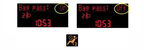
This function is activated as follows by means of the setup menu on the instrument panel:
- with the vehicle parked, press the MODE button to gain access to the setup menu;
- select the "Passenger bag" function by means of the + or - buttons;
- press the MODE button and, using the + or - buttons, select the "Passenger bag: Off (for deactivation) or the message Passenger bag: On (for activation); lastly, press the MODE button again to confirm.
When the function is on, the instrument panel warning light stays on.
KNEE BAG MODULE
Specifications
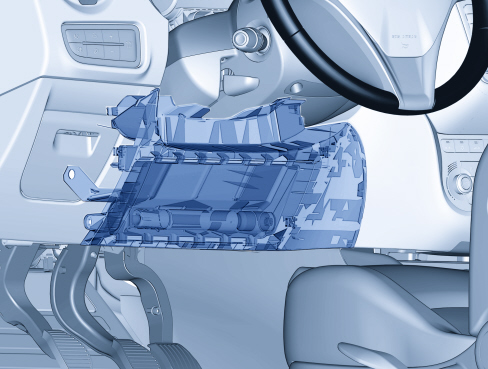
An air bag module is also available on request.This is fitted in the lower part of the fascia in front of the drivers' knees. This module, in addition to protecting the lower limbs, increases the overall level of protection provided to the driver, in particular preventing him/her from sliding forwards and possibly injuring the legs and chest.
Composition
The knee bag module consists of:
- a metal container;
- a gas generator;
- a nylon bag with a volume of around 16 litres;
- a plastic cover.
The container is fastened to a support plate and a safety plate that secures it rigidly to the lower part of the dashboard.
The plastic cover tears at preset points when activated to allow the bag to expand correctly.
Operation
The gas generator is electrically activated by means of a signal from the electronic control unit. Following this signal, pyrotechnic activation is triggered, causing the gas in the generator to expand. The expanding gases emerge through openings to inflate the bag.When the bag is inflated, the bag is in an optimum position to perform its role of protecting the occupant.
SIDE AIRBAG MODULE
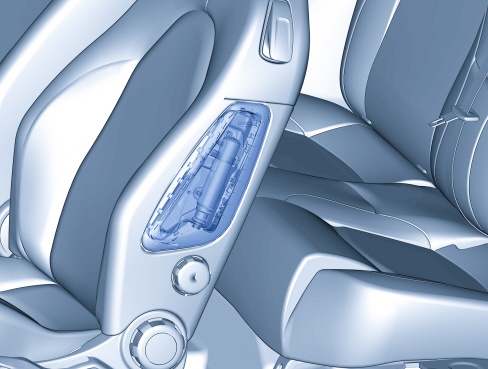
Specifications
To increase the level of protection offered by the body in the event of a side impact, two Side Bag modules have been provided in the front seats.
This device ensures the air bag is always in an optimum position in relation to the occupant, regardless of the angle of the seat or the size of the occupant.
The side bag protects the chest and pelvis areas and also - together with the door panels - protects critical areas of the body such as the ribs and abdomen.
Its position on the seat always guarantees maximum effectiveness regardless of the position of the latter even if the occupant is not sitting correctly because the opening dynamics of the bag minimise the risk of injury to the body caused by impact with the bodyshell.
|
|
Do not cover the front seat backrests with extra covers. |
|
|
Do not wash the seat backrest with water or steam under pressure. |
Composition
The side bag module consists of:
- a metal container;
- a gas generator;
- a nylon bag with a volume of around 12 litres;
- a plastic cover.
The plastic cover tears at preset points when activated to allow the bag to expand correctly.
The module is connected to the electrical system by means of two leads with yellow sheaths.These are contained, together with the seat earth connection lead, in a protective fabric-lined duct secured to the seat structure.
Operation
The gas generator is electrically activated by means of a signal from the electronic control unit. Following this signal, pyrotechnic activation is triggered, causing the gas in the generator to expand. The expanding gases exit through dedicated openings to inflate the bag. The bag's deployment causes the seams designed to yield easily on the backrest cover to yield, allowing the bag to open correctly.
When fully inflated, the bag is in an optimum position to protect the occupant.
|
|
It is not possible to carry out operations on seats fitted with air bags, apart from seat removing-refitting. Seats with air bags must not be dismantled. |
SIDE WINDOW AIRBAG MODULE
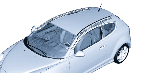
Specifications
The window bags are activated together with the side bags and place themselves between the occupant and the vehicle to prevent the head coming into contact with highly intrusive objects such as glass, pillars etc.
Because the window bags extend from the front pillar to the luggage compartment, they protect front and rear passengers. The window bag system offers the best performance due to the broad area covered and their ability to be self-supporting even without a backing.
Composition
The window bag module consists of:
- a gas generator secured by two bracket to the rear pillar;
- a metal connecting pipe between the gas generator and the bag;
- a bag with a volume of about 30 litres made from a permeable nylon fabric folded inside a container. The bag is designed to ensure, once fully inflated, correct absorption of impact energy while maintaining the occupants' heads at a proper distance from the impact area.Once fully inflated, the gas leaves the bag immediately through the porous fabric.
- plastic clips that secure the bag to the ceiling side rail;
- plastic references to secure the bag to the vehicle;
- a retaining strap secured to the front pillar that holds the bag in position once inflated;
Operation
The gas generator is electrically activated by means of a signal from the electronic control unit. Following this signal, pyrotechnic activation is triggered, causing the gas in the generator to expand.
On expanding, the gases escape via special openings and are evenly distributed along the entire bag.
The increase in bag volume causes the sleeve seams to yield and the trim to open.Everything is arranged so that the bag emerges correctly downward.
The bag is made to inflate correctly by a retaining strap on the front end of the bag.
When fully inflated, the bag is in an optimum position to protect the occupant.
The bag deflates immediately after being inflated by the gas because the fabric is permeable.
FRONTAL IMPACT SATELLITE SENSOR
SIDE IMPACT SATELLITE SENSORS
SEAT BELT PRETENSIONERS
Specifications
The pretensioners are pyrotechnic devices that are activated electrically by means of a signal from the electronic control unit.They are built into the reel of the front seat belts. Activation of the seat belt pretensioners is controlled by the same strategy as the air bags.
The pretensioners perform the function of recovering any slack in the seat belt and retaining the occupant against the backrest from the very start of the impact, thus reducing the overall movement of the occupant inside the passenger compartment.
The seat belt ree;s are also fitted with load limiters which decrease the force transmitted by the belts to the chest: the force level at which the limiters act is sufficient to considerably reduce the risk of fracturing shoulder blades and ribs, even in people with brittle bones (e.g. the elderly).
Operation
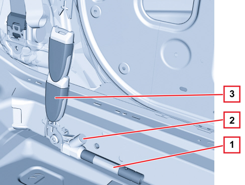
The pretensioner mechanism on the reel is illustrated in the diagram below.
1 - Gas generator
2 - Electrical connector
3 - Band
4 - Reel
When the car decelerates to a sufficient extent, as measured by the system accelerometers, the electronic sensor in the control unit sends a signal to trigger the gas generator pyrotechnic charges. The combustion of the propellant produces a chemical reaction, creating inert gas whose pressure produces a force that thrusts a piston upwards, changing the rotary movement of the reel into the opposite direction of the seat belt, rewinding it by a few centimetres.
|
|
Once the pretensioners have been activated, the belts are locked and must be replaced. |
Belt third point mounting pretensioner
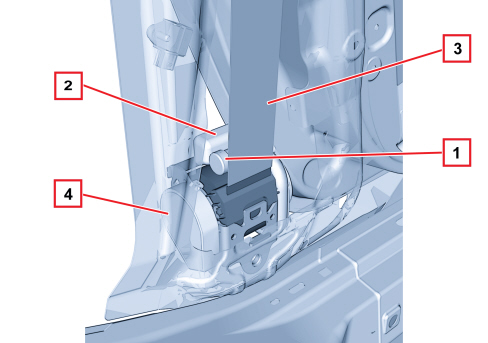
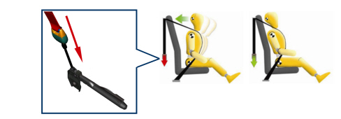
This vehicle also features a second electronically controlled, pyrotechnic type pretensioner, which acts on the seat belt mounting third point, drastically reducing the forward movement of the pelvis and legs and, therefore the violence of the impact of the shins and knees against the lower part of the dashboard.
In addition, the combined action of the two pretensioners, working at different points, almost totally eliminates slackness of the seat belt, keeping the effect of the occupant slipping under the seat, known as the submarining effect, to a minimum.
1. Gas generator
2. Electrical connector
3. Mounting third point rod
The device located on the mounting third point for the belt "pulls" the latter to prevent the passenger moving forward.
AIR BAG SYSTEM WARNING LIGHTS
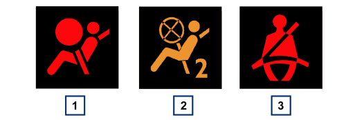
1 - Air Bag system fault warning light
2 - passenger side air bag disabling warning light
3 - seat belt not fastened warning light
Air bag system fault warning light
At key on, the fault warning light (red) comes on for about four seconds (initial self-diagnosis stage) and then goes off.
If no system faults are detected at key on and no fault conditions are present in the fault memory, the warning light goes off after four seconds of self-diagnosis.Otherwise it stays on.
The warning light remains lit or comes on during driving in the following instances:
- the control unit detects a fault in the air bag system;
- the control unit detects a crash with system activation.
As a consequence of a crash when the pretensioners or side bags alone are activated, the warning light stays on until system operating conditions are restored (replacement of affected part or control unit repair using an EXAMINER)
If the crash causes the front air bag modules to activate, the warning light stays on permanently because the control unit cannot reset (in this case the control unit must be replaced).
If, during the life of the control unit, internal operating errors are detected that cannot be reset by a EXAMINER, this is signalled by the permanent lighting up of the warning light.
Passenger air bag disabled warning light
At the key ON, the yellow passenger side air bag disabled warning light comes on for about four seconds (initial self-diagnosis stage).
The passenger Air Bag warning light flashes if the control unit detects a fault in the Air Bag system failure warning light.
Seat belt reminder - basic version without rear seat reminder
"first warning cycle": signalling via warning light
The "seat belts" warning light signals that the seat belt is not fastened (driver's or passenger side) coming on constantly from the Key ON.
"warning cycle": indication via warning light and buzzer
The warning light starts to flash and the buzzer sounds continuously for 6 seconds and then intermittently for 90 seconds if one of the following conditions is verified:
- Time elapsed 50 secs and vehicle speed above 10 km/h
- Vehicle speed above 20 km/h
- Distance travelled more than 400 m
If the seat belts are fastened during the cycle, the warning cycle is automatically interrupted and is only repeated if the seat belt not fastened condition is detected once again. The cycle is also interrupted when reverse gear is engaged (the warning light only remains on constantly) and is only repeated when the seat belt not fastened condition is detected once again and the vehicle speed exceeds 10 km/h.
Warning cycle exclusion mode
The driver can temporarily deactivate the warning cycle (the warning is activated again if there is a Key-OFF of more than 1 minute) by fastening the front seat belt(s) before the Key ON, holding it (them) for at least 20 secs with the key ON and undoing it (them) within 1 minute of the key-on.
The user can deactivate the warning cycle permanently only with the aid of the Technical Service dept.
The deactivation procedure must be carried out using a diagnostic instrument (Examiner) in communication with the instrument panel.
|
|
No one can deactivate the signal produced by the warning light in the dashboard.This is always present (fixed light) if the seat belt is unfastened. |
Warning cycle reactivation method
The driver can reactivate the warning cycle (if it is permanently deactivated) through intervention from the Aftersales Service Department or through a special item in the set up menu. This item disappears once the warning cycle is reactivated.
Seat belt reminder, front and rear seats
A reminder is present in some versions over the internal rear view mirror to inform all passengers, by means of a visual and acoustic indication, including the rear seat passengers, to fasten their seat belts.
The two side warning lights are associated to the front seats, while the three central warning lights are associated to the seat passengers.
The red and green warning lights work as follows:
- off if the seat belts are fastened at key-on;
- red if the front seat belts are not fastened;
- red blinking (rear seat only) if the front seat belts are not fastened;
- green if the seat belts are fastened.
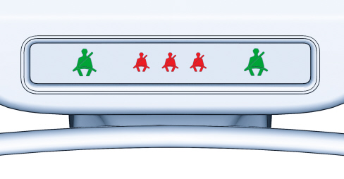
The first four warning lights will be red and the last will be green when only the driver is present and all seat belts are not fastened.
The three middle warning lights will blink for approximately 30 seconds and then light up fixed.
The behaviour of the front and rear seat warning lights is differentiated:
Driver:
If the driver is the only occupant, when 20 km/h is exceeded or when travelling at a speed from 10 to 20 km/h for longer than 5 seconds, an acoustic reminder sequence will be started (front seats) consisting of a tone for 6 seconds followed by a 90 second beep.The warning light will blink.
The warning lights will stay on fixed at the end of the cycle until the engine is stopped.
The acoustic reminder will be interrupted immediately when the driver's seat belts are fastened and the warning light will turn green.
The reminder cycle (acoustic and visual) will be repeated as described above if the seat belt is unfastened while travelling.
Passenger:
A similar solution applies for the front passenger, with the difference that the warning light turns green and the signal is interrupted also when the passenger leaves the car.
It both front seat belts are unfastened while the vehicle is travelling a few seconds apart, the acoustic indication will refer to the most recent event and the two warning lights will proceed with the visual indication independently.
Rear seats:
The reminder cycle is run only when any seat belt is unfastened. In this condition, the warning light referred to the seat belt which has been unfastened will start blinking for approximately 30 seconds.
An acoustic signal is also issued.
The visual indication will end independently for each warning light if several seat belts are unfastened.
|
|
All seat belts will stay on if at least one of the front seats is occupied and the seat belt is unfastened. All warning lights will go out (30 seconds after fastening the last belt) if both front seats are occupied, regardless of the rear belt state. All the warning lights will come on when at least one belt changes from fastened to unfastened status or vice versa. All warning lights will stay off if all seat belts are already fastened when the engine is started. |