CONSTRUCTION SPECIFICATIONS
VIEW OF ASSEMBLY
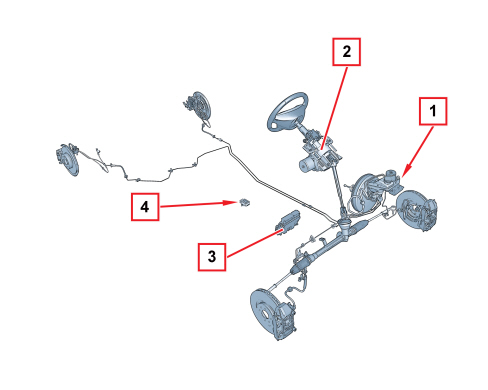
1 - ABS/VDC control unit
2 - Steering angle sensor built into the EPS (electric steering)
3 - Engine management control unit
4 - Yaw/lateral/longitudinal acceleration sensor
SPECIFICATIONS
The Bosch VDC 8.1 braking system, currently used is the most advanced available giving the best possible safety whilst driving. The VDC system, which incoporates the ASR/MSR/HBA/HHC functions, has been added to the ABS/EBD electrohydraulic control unit to achieve this.
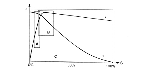
µ - Wheel grip
S - Slip
A - EBD intervention area
A - ABS intervention area
C - VDC intervention area
1 - Lateral force curve
2 - Longitudinal force curve
As can be seen from the grip/slipping diagram, the area covered by the VDC system is larger than that covered by a conventional ABS/EBD system.
The VDC system switches on automatically when the vehicle is started up and cannot be switched off by the user; the button in the centre console only switches off the ASR/MSR function and only when advisable (see ASR/MSR function).
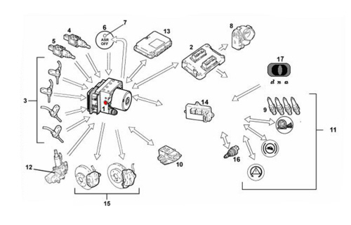
INPUT SIGNALS:
- Wheel speed sensors (from direct line) (3)
- Brake pedal sensor normally open (from direct line) (4)
- Brake pedal sensor normally closed (from C-CAN line) (5)
- Engine management control unit (from C-CAN line) (2)
- Throttle angle position (from NCM C-CAN line) (8)
- Body computer (14)
- Handbrake lever position (from C-CAN line)
- Warning light status signal (from C-CAN line) (11)
- Yaw sensor (Z) (rotation of vehicle on vertical axis) (from C-CAN line) (10)
- Lateral acceleration sensor (Y) (from C-CAN line) (10)
- Longitudinal acceleration sensor (X) (from C-CAN line) (10)
- Steering angle/steering wheel rotation sensor in electric steering (from C-CAN line) (12)
- Robotized transmission control unit on versions where fitted (gear engaged status) (from C-CAN line) (13)
- Hydraulic system pressure sensor (from direct line) (1)
- Reverse gear engagement sensor (16)
- Vehicle dyanmic control (17).
OUTPUT SIGNALS:
- Brake pressure modulation control (15)
- Ignition advance reduction control (from C-CAN line) (9)
- Engine power management control (from C-CAN line) (8)
- Gear change inhibition on versions with robotized gearbox (from C-CAN line) (13)
- Wheel speed signal for speedometer and milometer (from C-CAN) (14)
- VSO signal (vehicle speed) (14)
- ABS/ASR/VDC/HHC warning light in panel (from C-CAN line) (11)
VDC SYSTEM
Introduction
The VDC (Vehicle Dynamic Control) is an active safety system for controlling the vehicle during dynamic manoeuvres on the road in emergency conditions. In addition to integrating the ASR/MSR/HBA/HHC functions described previously, the VDC keeps the vehicle stable during sudden manoeuvres, especially on slippery surfaces. It reacts quickly to both vehicle oversteer and understeer, restoring stability and allowing the driver to maintain full control of the vehicle.
This has been achieved through the addition of special sensors: steering angle sensor and yaw/lateral acceleration/longitudinal acceleration sensor.
The VDC system is managed by the ABS electronic control unit, integrated with a special electro-hydraulic control unit that allows action on the braking system independent of the user's action.
The control unit processes the following signals:
- steering angle/steering wheel rotation speed sensor
- yaw/lateral/longitudinal acceleration sensor
- motorized throttle position
- wheel rpm sensors
- hydraulic braking system pressure sensor
and uses special algorithms in the electronic control unit software to obtain the figures for the dynamic control of the vehicle:
- longitudinal and transverse slip between the wheels and the road surface
- axle drift.
Using these figures, the system interprets the effective dynamics of the vehicle; having identified all the critical conditions resulting from environmental factors (e.g. surface with poor grip) or any errors made by the user (e.g. panic situations) and with subsequent intervention on the brakes and the drive torque, the vehicle is restored to good driving conditions.
The system interfaces with:
- E.C.M. (Engine Control Module) for regulating drive torque,
- B.C.M. (Body Computer Module) for the transmission of the vehicle speed and the control of the warning lights.
The exchange of information between these components takes place via the C-CAN line.
The K serial line is used to diagnose the system.
The system is combined with a power unit with a specific brake pump; in addition, the pipes between the brake pump and the ABS control unit have a larger diameter (6 mm) than normal pipes (4 mm); this is designed to prevent adverse effects on the operation of the VDC at low brake fluid temperatures.
Operating strategies
As described previously, in addition to controlling the slipping of the vehicle in a lengthwise direction, the VDC system also controls slipping in a sideways direction and, as a result, controls the lateral stability of the vehicle.
The lateral stability of a vehicle depends on the reaction of the tyres to lateral forces, and on the adhesion force of the wheel to the road surface.
It should be remembered that wheel grip depends on the vertical load and the wheel condition (loaded or unladen) and on the friction coefficient, which is in turn determined by the road surface and tyre conditions.
When the vehicle is travelling in a straight line, the lateral forces do not really have an effect unless outside factors intervene (e.g. a gust of wind or a change to a different surface) and increase their intensity, unlike when driving round a bend where there is a strong increase in lateral forces due to the increase in centrifugal force.
The action of the lateral forces produce a variation in the drift angle of the wheels and, consequently, a variation in the axle drift (drift angle = difference between the desired route and the effective route).
The lateral forces do not, however, act equally on all four wheels because they are not subject to the same load conditions. In fact, the load on the wheel differs according to the situation the wheel is in, namely:
- acceleration (lightening of the front axle and loading of the rear axle)
- braking (loading of the front axle and lightening of the rear axle)
- bend to the right/left (loading of the outer wheels and lightening of the inner wheels)
- accelerating/decelerating round a bend (combination of the cases mentioned above).
It is obvious that if the lateral forces acting on the individual wheels vary, there will also be a variation in the forces acting on the vehicle axles; consequently the lateral forces acting on the front axle overcome those on the rear axle and vice versa, determining a rotation (moment) on the vertical axis of the vehicle (yaw axis).
The yaw moment affects the behaviour of the vehicle, producing either understeer or oversteer.
UNDERSTEER:
understeer for a vehicle is when, with increasing lateral acceleration, the drift angle for the front axle increases greatly compared with that of the rear axle. When this happens, the vehicle tends to go straight ahead (taking the bend wide) when cornering.
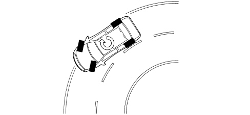
OVERSTEER:
oversteer for a vehicle is when, with increasing transverse acceleration, the drift angle for the rear axle increases greatly compared with that of the front axle. In this case the vehicle tends to turn around on itself (the rear axle tends to go straight on, causing the vehicle to cut the corner).
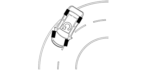
To keep the effect of lateral forces under control and limit the yaw moment, the ABS control unit calculates the nominal behaviour of the vehicle by means of:
- steering angle sensor
- accelerator pedal position
- brake pedal pressure
the control unit compares these parameters with the actual behaviour of the vehicle by means of:
- vehicle speed sensor (active sensors on the wheels),
- yaw/lateral acceleration sensor
if the values differ from the normal operation of the vehicle, the control unit is capable of:
- detecting actions carried out by the user, i.e. the steering wheel reveals the number of degrees (wide radius or narrow radius bends) and the rotation speed of the drive wheels (abrupt or gradual turns) and the throttle position and the brake pressure when accelerating or braking indicates how the user is taking the bend or deviating from a straight line.
- detecting the actual behaviour of the vehicle given the environmental variables, e.g. slippery surface, gusts of wind, reaction of the vehicle to incorrect manoeuvres by the user, etc., in order to identify the yaw moment and the lateral sliding of the axles via the sensors on the four wheels and the yaw/lateral acceleration sensor.
These operations are necessary to superimpose the mathematical model mapped in the control unit on the effective behaviour of the vehicle, in order to identify the vehicle's state (understeer or oversteer) and to decide the action for the brakes and the engine management
UNDERSTEER ON CORNERS
The control unit detects the presence of understeer (mainly from the drift of the front axle), corrects the behaviour of the vehicle, braking the inner front and rear wheels round the bend in order to create an opposing moment which will lead the vehicle towards the centre of the bend and, possibly, reduce the drive torque.
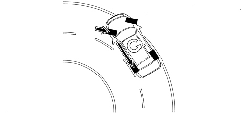
OVERSTEER ON CORNERS
The control unit detects the presence of understeer (mainly from the drift of the rear axle) and corrects the behaviour of the vehicle, braking the outer front wheel round the bend in order to create an opposite yaw moment. In certain cases, in addition to the action on the brakes, there is also an increase in the speed of the inner drive wheel round the bend.

|
The system intervenes before the oversteer and understeer values are too high, in order to prevent the countersteering manoeuvre from making handling difficult. |
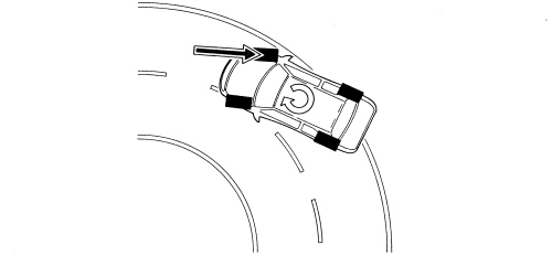
ABRUPT VARIATIONS FROM A STRAIGHT PATH (SLALOM/OVERTAKING)
In the event of sharp variations from the path (e.g. overtaking, slalom), the control unit identifies possible oversteer and understeer conditions and corrects the path of the vehicle, acting as described previously.
Sharp variation from the straight path (gusts of wind, driving on different surfaces)
The control unit is capable of detecting deviations in the path and the prevalence of axle drift, and correcting the path through suitable action on the brakes and the engine.
ABRUPT ACCELERATION/DECELERATION
The control unit deploys the ASR/MSR strategy, while also controlling vehicle lateral acceleration and, as a result, the action on the brakes and drive torque.
Exclusion of ASR/MSR system
If the ASR/MSR function is cut out, the following functions remain activated:
- ABS/EBD
- TC up to a speed of 40 km/h
- VDC with intervention of the brakes only.
- HHC
VDC INTERVENTION DISPLAY
The intervention of the VDC system is shown by the special warning light in the instrument panel flashing (5 Hz d.c. 50%).
|
|
The VDC system improves driving safety, but there are limited situations which cannot be controlled by the VDC system, therefore it is not seen as a device which improves the performance of the vehicle but as a device that improves the safety of the vehicle. |
Asr/msr function
This system, in addition to the normal anti-lock and brake force distribution functions controlled by the ABS with EBD, also carries out the following functions:
- acceleration slipping adjustment (A.S.R.)
- adjustment of the engine braking torque (M.S.R.)
- locking the differential through action on the brakes (T.C.).
These functions are carried out through action on the drive torque (ASR/MSR) and the application of a braking force on one or both the drive wheels (TC).
If, during acceleration, one or both the drive wheels tend to slip, the ASR system asks the engine management control unit to reduce the torque transmitted to the wheels. Almost simultaneously, it brakes the wheel or wheels without any intervention by the user (TC)
If the wheels tend to lock during heavy deceleration, the MSR system requests that the engine management control unit adjusts the engine braking torque in order to prevent the vehicle becoming unstable.
The system can be bypassed by operating the button on the dashboard next to the Hazard pushbutton (hazard lights).
The LED in the button comes on and the display in the instrument panel signals that the ASR/MSR system has been switched off.
The warning light in the panel coming on indicates that the system is excluded on account of a fault recorded by the control unit.
The intervention of the ASR/MSR is signalled by the flashing of the warning light in the instrument panel.
Each time the vehicle is started up, the ASR/MSR function is activated even if the function was switched off when the vehicle was switched off.
The system works through signals coming from the active sensors for the four wheels, from the brake light switch and from the ASR on/off button.
It continuously compares the speed of the wheels on the same side of the vehicle (right front with right rear and left front with left rear) and when a difference in speed of more than 2-6 km/h (intervention level) is detected between two wheels on the same side, it intervenes with the ASR logic.
The ABS/ASR control unit communicates continuously with the engine management control unit via the C-CAN line.
Slipping of the drive wheels
Intervention - intervention times for good road grip conditions
Drive torque reduction by the engine management control unit through the alteration of the ignition advances, 6/100 of a second after the slipping limit is exceeded.
A further reduction in torque through a decrease in the throttle opening (by the engine management control unit through the motorised throttle body after 15/100 of a second).
Intervention of the hydraulic system (braking force on the drive wheels) after 2/10 of a second.
Operation in poor grip conditions
The system is capable of recognizing these conditions by comparing the acceleration of the drive wheels with the torque transmitted by the engine (engine load from the engine management control unit).
The system behaves as for both drive wheels slipping in good road grip conditions and the intervention levels are at the lower limit.
Slipping of one drive wheel only
Intervention - intervention times
Torque reduction by the engine management control unit through the alteration of the ignition advances, 6/100 of a second after the limit is exceeded.
A further reduction in torque through a decrease in the throttle opening (by the engine management control unit, through the motorised throttle body) after 15/100 of a second.
Intervention of the hydraulic system: a braking action exerted on the wheel that is slipping to guarantee a resistive force on the side with poor grip (T.C.).
This resistive force allows the differential to transmit an equal torque with good grip.
Slipping of one wheel round bends in good grip conditions
The system recognises the bend from the speed of the rear wheels (driven).
The system implements the same operating mode described for the "Slipping of one drive wheel only" condition, with the intervention levels at the upper limit. The torque reduction is applied gently.
Slipping of one wheel round bends in poor grip conditions
The system implements the same operating mode described for the "Slipping of one drive wheel only" condition, with the intervention levels at the lower limit. The torque reduction is accentuated (to ensure good lateral vehicle hold).
|
|
In the ASR intervention conditions with the control unit simultaneously receiving the signal coming from the brake light switch, the system excludes intervention on the brakes. The section relating to the torque reduction remains activated. |
|
|
With the brake light switch activated and maximum braking pressure (e.g. heel point, switch defective, etc.), if the system detects a difference in speed between the two front and rear wheels which implies the intervention of the ASR, the torque reduction only is implemented. Intervention on the brakes is excluded. |
Adjustment of engine braking torque during deceleration
Vehicle instability during deceleration in poor grip conditions
The system recognises this condition from the engine load, from the speed of the front and rear wheels and from the brake pedal sensor. In this case there is an increase in drive torque through the intervention of the engine management control unit opening the motorized throttle to overcome the natural instability of the vehicle owing to the engine braking torque in poor grip conditions.
ASR/MSR function exclusion
If the function is excluded using the button on the dashboard, which is advisable when the vehicle is on certain surfaces (e.g: deep snow, deep mud, thick sand or gravel) or chains are fitted to the drive wheels, the ABS/EBD system remains activated.
Intervention levels
The different intervention levels between 2 and 6 km/h depend on environmental factors; some of the conditions have been described in the operating logics, others are:
- high acceleration level, high threshold
- vehicle speed (see graph)
- type of tyres (normal or winter): with winter tyres and good grip, high intervention levels; with winter tyres and poor grip, low intervention levels. The system is capable of recognizing these conditions by comparing the acceleration of the drive wheels with the torque transmitted by the engine (engine load from the engine management control unit).
|
|
The ASR/MSR function is active at all vehicle speeds but the braking effect is cut out above 80 km/h. |
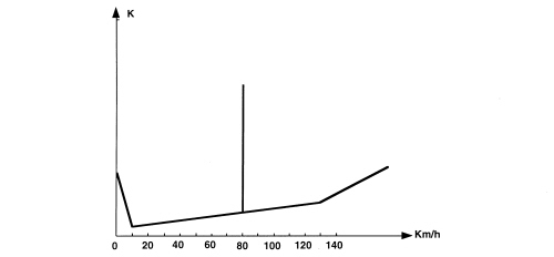
K - Slipping level
ASR/MSR SYSTEM FAILURE
In the case of a failure of the ABS system, the ASR system is also disabled. The following problems exclude the ASR system only:
- engine C-CAN message errors
- C-CAN bus errors.
When these problems occur, the control unit activates the warning lights on the instrument panel and on the button.
The warning light strategy is shown in the Warning Light Operation table.
The warning lights are operated by the ABS control unit via the C-CAN, as for the ABS/EBD system.
Operation of the hydraulic system
The electrohydraulic unit on the versions equipped with ASR has 4 additional solenoids.
When the (normally closed) intake solenoid is activated, the additional quantity of fluid required to increase the pressure and brake the wheel(s) can be received.
When the (normally open) control solenoid is activated, it allows the modulated pressure produced by the pump - necessary for the intervention of the ASR - to be maintained in the brake calliper-pump circuit.
With the ASR function not switched on, the electronic control unit:
- does not supply the (N.C.) intake solenoid (2).
- does not supply the (N.A.) solenoid (3).
In this way the system operates during the following stages:
- pressure increase
- pressure maintenance
- pressure reduction
- pressure increase and resupply.
Hba function
Introduction
It has been demonstrated that in emergency conditions not all drivers manage to produce the best possible performance from their vehicle's braking system. In effect, although many manage to apply the brakes quickly, the force applied is limited.
There are two effects of this limitation: the first is linked to the fact that the braking force is the same as in normal conditions; the second is linked to the psychological fear of locking the wheels, even knowing that ABS is available. In these conditions, emergency braking assistance is carried out by increasing the pressure in the system in direct proportion to the effort applied by the driver.
The same vehicle deceleration is produced with a load reduced by a third compared with normal braking. In addition, as is known, vehicle stopping distances depend not only on the braking distance but on the distance travelled during the braking reaction time and rest time. By reducing the latter, the device allows the stopping distance to be reduced, especially at high speeds.
Operation
The HBA function (Hydraulic Brake Assist) is carried out by the ABS control unit using VDC software, which controls the oil pressure uphill gradient when the brake is pressed.
Emergency braking conditions are recognised when this gradient exceeds the set level.
The device's speed level is set so that it only intervenes in actual emergency conditions without in any way affecting the manoeuvrability of the pedal in normal vehicle usage conditions.
Hhc function
Introduction
The HHC function (Hill Holder Control) is designed to assist the driver during departures in forward gears or reverse when the gradient of the road is more than 2%. In effect, the HHC is capable of automatically providing sufficient braking torque to keep the vehicle stationary until the clutch is fully released and the engine torque is sufficient to start the vehicle comfortably.
Operating strategy
The HHC is automatically activated when the brake pedal is pressed in conjunction with the following conditions:
- vehicle speed equal to zero,
- gradient more than 2%,
- clutch pedal pressed.
The moment the brake pedal is released, with all other conditions being equal, the HHC keeps the braking system pressurised for 1.5 seconds to allow the driver to move his/her foot from the brake pedal to the accelerator pedal, without the vehicle moving and without using the parking brake.
Once the accelerator is pressed, the HHC continues to keep the vehicle still for a further 1.5 seconds or until the engine torque is sufficient to start the vehicle.
The time indicated (1.5 + 1.5 secs.) is a maximum time that the control unit varies (i.e. reduces) if the sequence of driver movements (brake pedal/acceleration/sufficient torque) is quicker.
Conversely, if the driver does not press the accelerator within the first 1.5 seconds following the release of the brake pedal or the necessary torque is not reached within the additional 1.5 seconds, the HHC removes the pressure from the hydraulic circuit, so that the removal is not sudden.
In poor grip conditions the HHC is switched off for better vehicle control. This is because when stopped on an icy incline, if the HHC keeps the wheels locked but the vehicle slips backwards, it does not manage to produce minimum control of the vehicle. If the wheels are released, however, it is possible move backwards, keeping a straight line path.
A slipping recognition test lasting about 150 ms has been designed for these extreme conditions and is implemented when the ABS or ASR is activated or one of the wheels locks just prior to the engagement of the HHC.
During the test stage the control unit (using the ABS parameters) defines which wheel is the most stable and then discharges the braking pressure for this wheel, keeping the other three braked.
If the speed sensor for the wheel which is not braked reports a speed other than zero, this means that the vehicle is moving even though all the other wheels are locked; this indicates poor grip conditions, therefore the HHC will switch off, releasing the pressure in the entire braking circuit.
Conversely, if the wheel that is not braked remains still, this means that the situation is stable and the HHC will continue to work.
BASIC FEATURES
Specifications:
- automatic engagement with speed at zero and vehicle gradient > 2%
- management of NQS failure warning light
- pressure maintenance time of 2 + 10 secs.
- automatic switching off prior to acceleration, clutch release or exceeding of maximum time from brake pedal release.
Necessary sensors and signals: :
- reverse gear engaged from C-CAN
- clutch status from C-CAN
- accelerator pedal status from C-CAN
- brake pedal status from C-CAN
- engine torque value from C-CAN
- engine rpm from C-CAN
- longitudinal or incline sensor from C-CAN
- brake pressure sensor (incorporated in VDC control unit)
- Wheels stationary from rpm sensor signal
Dst function
Introduction
The DST function (Dynamic Steering Torque) is in the VDC control unit software and is capable of improving handling in all driving conditions interacting with the steering control unit.
When the vehicle loses stability, the VDC system interacts with the steering control unit which supplies additional torque at the steering wheel for the correct manoeuvre to be carried out. In practice the system suggests the correct manoeuvre to make by slightly modulating the steering power assist function giving the driver the feeling of having complete control over the vehicle.
The active steering control DST function is made up of three subfunctions:
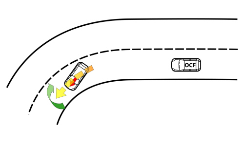
OCF (Oversteering Compensation Function)
When the vehicle is in oversteer conditions, the steering control unit counter-steers automatically even before the VDC-ABS system intervenes.
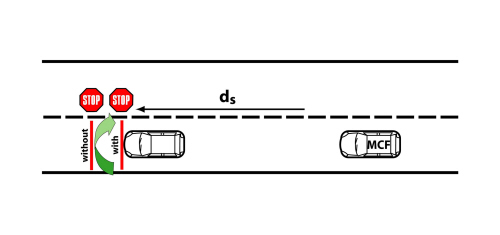
MCF (μ-split Control Function)
In driving conditions on road surfaces with different grip (for example: two wheels on ice and two on asphalt), the steering control unit automatically counter-steers even before the VDC-ABS system intervenes, reducing the vehicle stopping distance.
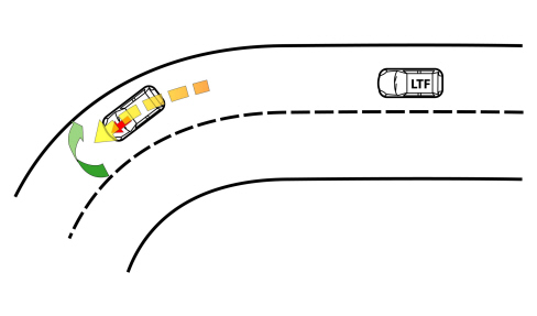
LTF (Linearization Torque Feedback)
When tackling a wide bend, in sporty driving conditions (from 0.6 g), as well as a certain steering angle the driver notices a lightening of the steering wheel, and consequently a feeling of losing stability. In these conditions, the electric steering control device control unit provides an increase in resistence torque at the steering wheel, which decidedly improves the feeling of vehicle control.
The DST system intervenes for medium/high lateral acceleration.
This innovative function "communicates" with the driver and suggests the most suitable interventions for keeping the vehicle in control and for optimum handling.
The driver feels more in control of the vehicle and realises more gradually that they are nearing the road holding limit: this allows smoother intervention of the stability control and guarantees more pleasant driving and improved safety with a less intrusive intervention of the VDC.
Ttc function
Introduction
The TTC function (Torque Transfer Control) simulates the action of a self locking differential by acting only on the brakes.
This advanced function is the integration of different vehicle components:
- VDC;
- rpm sensors on every wheel;
- sensor on the accelerator;
- steering angle sensor;
- lateral acceleration sensor;
- yaw sensor.
The intervention of the TTC is especially noticeable during limit 'pull' and 'release' manoeuvres when cornering. Responsiveness when cornering is improved thanks to the improved drive.
During the 'pull' stage, without TTC, the inner wheel, with less load, slides more and, where an ordinary differential is fitted, there is a reduction in the traction capacity on the entire axle.
At the same time, a reduction in the lateral forces is produced through the traction effect, causing the extension of the trajectory (understeer).

When the TTC intervenes on the other hand, the VDC control unit brakes the inner wheel producing a load for the drive torque on the corresponding driveshaft which allows a similar torque to be transferred to the outer wheel in grip conditions.
This action is aimed at improving movement when cornering and containing understeer.
The TTC operation is perceptible as long as the available grip at the outer wheel is sufficient; when this wheel also starts to slip the operation of the TC (Traction Control) cuts in with the cut off of torque/action at the brakes.
Warning light operation
The control unit activates the warning lights according to the following logic:
|
System status |
ASR warning light on button |
EBD warning light in NSQ |
ABS warning light on NSQ |
VDC warning light in NSQ |
HHC warning light on NSQ |
|
|
Check (4s) |
EBD/ABS/ASR/ESP/HHC OFF for the first 500 ms |
ON |
ON |
ON |
ON |
ON |
|
Whilst driving |
EBD/ABS/ASR VDC/HHC ON |
OFF |
OFF |
OFF |
OFF |
OFF |
|
ASR switched off by button (1) |
EBD/ABS/HHC VDC (2) ON ASR OFF |
ON |
OFF |
OFF |
OFF |
OFF |
|
EBD faulty |
EBD/ABS/ASR/VDC/HHC OFF |
ON |
ON |
ON |
ON |
ON |
|
ABS faulty |
EBD ON ABS/ASR/VDC OFF HHC ON/OFF |
ON |
OFF |
ON |
ON |
ON |
|
ASR faulty |
EBD/ABS ON ASR/VDC OFF HHC ON/OFF |
ON |
OFF |
OFF |
ON |
ON/OFF (3) |
|
HHC faulty |
EBD/ABS/ ASR/VDC ON HHC OFF |
OFF |
OFF |
OFF |
OFF |
ON |
|
VDC faulty |
EBD/ ABS/ASR ON VDC OFF HHC ON/OFF |
OFF |
OFF |
OFF |
ON |
ON/OFF (3) |
|
Insufficient brake fluid level or parking brake on |
EBD/ABS/ASR/ VDC/HHC ON |
OFF |
ON |
OFF |
OFF |
OFF |
|
ASR/VDC faulty |
EBD/ABS/ASR/ VDC/HHC ON |
OFF |
OFF |
OFF |
Intermittent 4Hz d. c. 50% |
OFF |
|
HHC in action |
EBD/ABS/ VDC/HHC ON |
OFF |
OFF |
OFF |
OFF |
ON |
(1) the switching off of the system ends with the key-off, at each new key-on the system is automatically switched back on.
(2) VDC operation limited to operation on the brakes.
(3) It is dependent on the type of fault; if the exhaust valves, the speed value and the communication on the C-CAN are available, the function is maintained and the warning light is OFF.
|
|
The system is diagnosed via the C-CAN. The system can be diagnosed by connecting the diagnostic equipment to the diagnostic socket on the NBC (body computer node). |
Component description
Operation of the hydraulic system
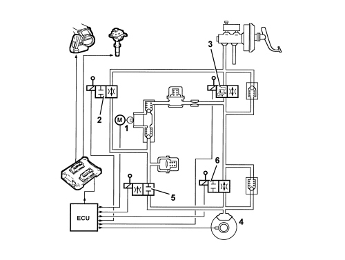
The electr-hydraulic unit on the version equipped with VDC has 4 additional solenoid valves.
When the (normally closed) intake solenoid is activated, the additional quantity of fluid required to increase the pressure and brake the wheel(s) can be received.
When the (normally open) control solenoid is activated it allows the modulated pressure produced by the pump, necessary for the intervention of the VDC, to be maintained in the brake caliper-pump circuit.
With the brake pedal pressed, the electronic control unit:
- does not supply the (N.C.) intake solenoid (2).
- does not supply the (N.A.) solenoid (3).
In this way the system operates during the following stages:
- pressure increase
- pressure maintenance
- pressure reduction
- pressure re-supply and increase
- as for the ABS/EBD.
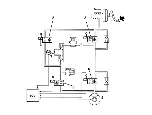
When the control unit detects the activation of the VDC function, it:
- supplies the hydraulic assembly pump (1)
- supplies the (N.C.) intake solenoid (2)
- supplies the (N.A.) control solenoid (3).
Therefore the pressure produced by pump (1) reaches the brake caliper and is modulated, on the request of the electronic control unit, by the discharging solenoid (5) and the pressurizing solenoid (6).
Electrohydraulic unit
The electrohydraulic unit consists of an electronic control unit and a hydraulic control unit:
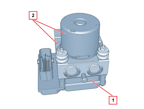
1. Electronic control unit
2. Electrohydraulic control unit
ELECTRONIC CONTROL UNIT
The electronic control unit carries out the following functions:
- acquires the data coming from the wheel active sensors
- memorizes the control parameters defined during the vehicle P.D.I.
- memorizes the control software
- processes the data acquired
- controls the braking process
- detects faults in the braking system components
- memorizes the fault codes and activates the ABS/EBD/ASR/VDC/HHC warning lights via the C-CAN line
- transmits and receives data via the diagnostic connector
- communicates with the engine management control unit via the C-CAN line
- controls the ASR function switching on/off process
- transmits and receives data via the C-CAN line.
The control unit is conected to the electrical system via a 38 pin connector.
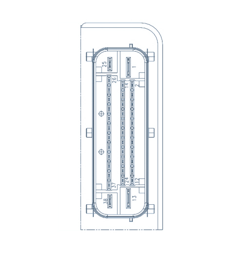
1. Pump +30 supply
2. + 15 power supply
3. Right front sensor power supply
4. Right front sensor signal
5. C CAN H
6. C CAN L
7. VSO
8. Not connected
9. Not connected
10. Right rear sensor signal
11. Right rear sensor power supply
12. Brake light switch
13. Pump earth
14. Not connected
15. Not connected
16. Not connected
17. C CAN H
18. C CAN L
19. Not connected
20. Not connected
21. Not connected
22. Not connected
23. Not connected
24. Not connected
25. +30 solenoid power supply
26. ASR bypass switch
27. Left front sensor power supply
28. Left front sensor signal
29. Not connected
30. Warning light on ASR button
31. Not connected
32. Not connected
33. Not connected
34. Diagnostic K line
35. Left rear sensor signal
36. Left rear sensor power supply
37. Not connected
38. Solenoid earth
It performs the function of modulating the pressure of the fluid at the brake calipers via solenoids, with the following operating stages:
- brake fluid pressure increase
- brake fluid pressure maintenance
- brake fluid pressure decrease.
ELECTROHYDRAULIC CONTROL UNIT
|
|
The hydraulic control unit with VDC includes a sensor for monitoring the braking pressure, which cannot be replaced on its own. |
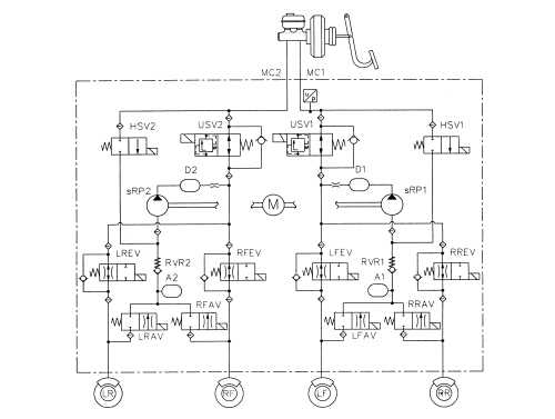
The electrohydraulic control unit consists of:
- twelve 2-way solenoids
- a dual circuit scavenging pump
- two low pressure accumulators
- two high pressure accumulators
- brake pressure sensor.
Active sensors
SPECIFICATIONS
System details
The adoption of active sensors offers the following advantages:
- a reduction in sensitivity to electromagnetic interference
- a saving in weight and size
- a simplification of the transmission couplings through the elimination of the phonic wheels.
Thanks to the possibility of detecting very low speeds, the active sensors improve the precision of the on-board navigation systems.
These systems update the position of the vehicle in the memorised maps via the GPS system: continuous information about the route travelled by the vehicle, even at low speeds, is therefore essential in calculating its exact position.
Composition
Structure
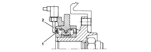
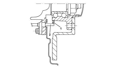
The active sensors consist of two fundamental components:
- a multipolar magnetic coding device (1) built into the wheel hub bearing (complete with controls)
- a Hall effect receiver (2) that faces the coding device.
FRONT SENSOR
REAR SENSOR
Operation
The active sensor functions on the basis of variation in the internal electrical resistance, according to the intensity and direction of the lines of force of an external magnetic field (multipolar magnetic coding device). It produces a variable square wave signal whose frequency varies according to the rotation speed of the wheel, but has a constant amplitude.
The active sensor is therefore a proximity sensor with a built-in electronic system, connected by means of a cable to the ABS control unit, from which it receives an electrical supply and to which it transmits the speed of the vehicle.
The phonic wheel is a multipolar ring, an elastomer with a certain number of magnetic particles which are lined up using a special magnetisation technique to form several magnets with alternate North or South polarity in a circumferential direction.
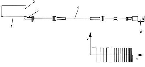
1. Magnetized sealing ring
2. Bearing
3. Sensor head
4. Active sensor
5. Sealed connector
ABS/VDC system piping
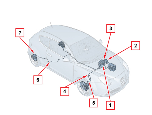
1. Brake control pump
2. ABS/VDC control unit
3. Piping from brake pump to ABS/VDC control unit
4. Rigid pipes for front brakes
5. Front caliper hoses
6. Rigid pipes for rear brakes
7. Rear caliper hoses
The ABS pipes can be divided into two groups:
- rigid connecting pipes from the ABS control unit to the front and rear flexible brake connecting pipes. The rear brake pipes are divided into two sections, for fitting requirements, and they are protected by a special shield in the section exposed to the risk of damage.
- flexible connecting pipes between the rigid pipes and the brake calipers.
The rigid and flexible pipes are secured to the body by special brackets and/or fastening clips.
Steering angle sensor
SPECIFICATIONS
The steering angle sensor has the task of measuring the angles in degrees and the rotation speed of the steering wheel and making these figures available via the C-CAN (steering angle sensor node).
LOCATION
The steering angle sensor is fitted inside the electrical steering and is not available from the Parts Dept. on its own. Replacement of the steering angle sensor together with the electric steering requires the system to be reset and initialised using an Examiner.
Yaw/lateral/longitudinal acceleration sensor
SPECIFICATIONS
The yaw/lateral/longitudinal acceleration sensor detects rotation on the vehicle's vertical axis (yaw) and measures lateral and longitudinal acceleration (the latter in order to assess vehicle tilt).
Connection to the VDC control unit is via the C-CAN line.
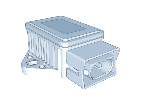
The sensor has the following functional specifications:
Supply voltage:
- Minimum value 8.2V
- Maximum value 16V
- Rated value 12V
Operating temperature:
- Minimum value -40°C
- Maximum value +85°C
Current absorption at 12 V:
- Rated value 70mA
Yaw sensor:
- Measurement range ± -100 °/s
- Resolution ± -0.3°/s
Lateral acceleration sensor:
- Measurement range ± -1.8 g
COMPOSITION
The sensor consists of a plastic casing that houses the sensitive elements which detect yaw, lateral acceleration, longitudinal acceleration/deceleration, and the associated electronic management.
The sensor has a connector with six pins, all of which are connected.
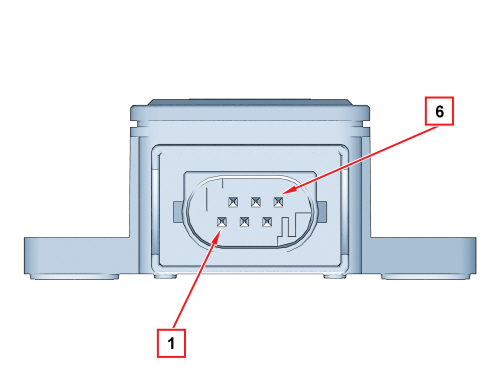
1. VIGN (+15 start-up)
2. CAN-H line
3. CAN-L line
4. CAN-H line
5. CAN-L line
6. Earth
Location
The sensor is located under the heater unit; refer to
Op. 3350E30 LATERAL ACCELERATION AND SLEWING SENSOR - R.R
OPERATION
The sensor receives a direct power supply from the ABS control unit and simultaneously provides the yaw and lateral or longitudinal acceleration signal via the sensitive elements.
The yaw signal is processed directly by the sensor and is supplied to the ABS control unit with a reference signal superimposed.
The yaw signal has a range of between:
- lower limit 0.65V
- upper limit 4.35V
- reference signal 2.5V.
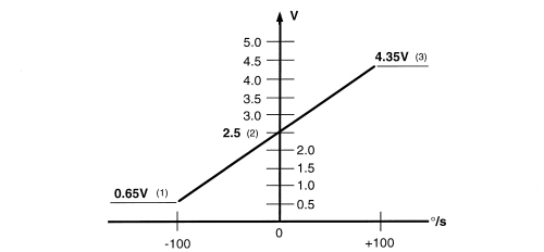
1 - Upper limit
2 - Reference signal
3 - Lower limit
The sensor provides the ABS control unit with a signal for fault diagnosis and safety functions.