CONSTRUCTION SPECIFICATIONS
The Bosch Motronic ME7.9.10 system, for petrol and LPG dual fuel operation, belongs to the following category of integrated systems:
- inductive discharge, digital, electronic ignition
- solid state distribution
- sequential, phased type electronic injection (1-3-4-2).
The list of additional components for the LPG system is as follows:
- LPG level sensor on tank
- LPG pressure and temperature sensor on the LPG manifold
LPG cut out solenoid valve relay switch on the tank
- LPG cut out solenoid valves on the tank
- solenoid valve and pressure reduction unit/vaporiser
- LPG/petrol switching button and instrument panel with built-in residual LPG level gauge
- LPG injectors
- petrol pump cut out relay
- petrol/LPG injector control SDU (Smart Driver Unit).
Here below are described the components specific to LPG injection; that not included
See descriptions 1056 PETROL INJECTION SYSTEM
Operating diagram
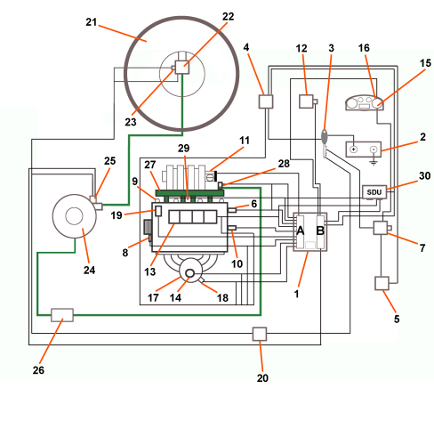
1. Petrol/LPG integrated injection-ignition electronic control unit
2. Battery
3. Ignition switch
4. Engine compartment junction unit
5. Climate control system relay
6. timing sensor
7. Body Computer (diagnosis socket and Alfa CODE signal)
8. rpm and TDC sensor
9. Spark plugs
10. Engine coolant temperature sensor
11. Throttle control actuator and throttle position sensor
12. Accelerator pedal potentiometer
13. Ignition coils
14. Oxygen sensor (upstream)
15. Injection system failure warning light
16. Rev counter
17. Catalytic converter
18. Oxygen sensor (downstream)
19. Phase transformer pilot solenoid
20. LPG cylinder solenoid valve control relay switch
21. LPG cylinder
22. LPG intake solenoid valve
23. LPG level sensor
24. Pressure reduction unit/vaporiser
25. LPG cut-out solenoid valve
26. LPG filter
27. LPG injector assembly
28. LPG pressure/temperature sensor
29. Knock sensor
30. Petrol/LPG injector control SDU (Smart Driver Unit)
DIAGRAM OF INFORMATION ENTERING/LEAVING THE CONTROL UNIT
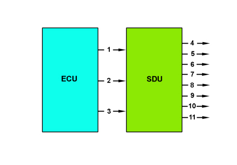
1. injector control
2. Petrol injector enablement
3. LPG injector enablement
4. LPG 1 injector
5. LPG 2 injector
6. LPG 3 injector
7. LPG 4 injector
8. Petrol injector 1
9. Petrol injector 2
10. Petrol injector 3
11. Petrol injector 4
LPG COMPONENTS RECOVERY AND SELF-DIAGNOSIS
The ECU carries out the input/output diagnosis, cyclically checking the signals and, in case of malfunctions, storing the relevant codes in the EEPROM (passive self-diagnosis).
The fault diagnosis carried out and the recovery actions in the case of a fault in the following components are reported.
Lpg level sensor on tank
The electronic unit carries out the following electrical fault diagnosis on the signal coming from the LPG level sensor every 0.1 secs.:
- short circuit to earth
- short circuit to battery or open circuit.
If a failure is detected, the control unit implements the following recovery action:
- return to petrol operation and consequent lighting of PETROL mode warning light in the instrument panel.
Lpg pressure and temperature sensor on rail
The electronic unit performs the following electrical diagnosis on the signal from the rail LPG pressure sensor:
- short circuit to earth
- short circuit to battery or open circuit
- LPG pressure signal plausibility.
This diagnosis is possible in all conditions, irrespective of the operating mode.
Both petrol operation and LPG operation and switching between the two operating modes is permitted.
The MIL warning light in the instrument panel comes on at the first cycle (driving cycle) where the LPG low pressure error is confirmed.
The MIL warning light in the instrument panel comes on at the third cycle (driving cycle) where the LPG temperature error is confirmed.
Lpg injectors
The electronic unit cyclically carries out an electrical fault diagnosis on the LPG injectors signalling the following problems:
- injector cold side open circuit
- injector cold side short circuit to earth
- injector cold side short circuit to Vbattery.
If a fault is detected, the control unit implements the following recovery actions:
- return to petrol operating mode
- warning light in instrument panel lit up.
Petrol/lpg injector control sdu (smart driver unit)
The electronic unit performs diagnosis on:
- petrol injectors control.
If a fault is detected, the control unit implements the following recovery actions:
- return to petrol operating mode
- warning light in instrument panel lit up.
Lpg cut-out solenoid valves relay switch
The electronic unit performs an electrical diagnosis on the LPG cut-off solenoid valve relay switch coils and signals the following faults:
- short circuit to earth or open circuit: this diagnosis is possible only in petrol operating mode
- short circuit to Vbattery: this diagnosis is possible only in LPG operating mode.
If a fault is detected, the control unit implements the following recovery actions:
- return to petrol operating mode
- warning light in instrument panel lit up.
CONTROL UNIT PIN OUT
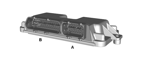
Connector B
1. Supply (1 A)
2. RF earth
3. Not connected
4. Not connected
5. Not connected
6. Not connected
7. RF earth
8. Sensor earth
9. Sensor earth
10. Not connected
11. Not connected
12. Low speed H-CAN line
13. H-CAN line
14. Main relay supply
15. Not connected
16. Not connected
17. Not connected
18. Not connected
19. Not connected
20. Sensor power supply (+5 V)
21. Not connected
22. Not connected
23. Not connected
24. H-CAN line
25. RF earth
26. Engine earth
27. Main relay supply
28. Engine earth
29. Not connected
30. Not connected
31. Not connected
32. Petrol injector enablement
33. LPG level sensor signal
34. Not connected
35. Not connected
36. Not connected
37. Not connected
38. Low speed L-CAN
39. L-CAN
40. Not connected
41. Not connected
42. Not connected
43. LPG injector enablement
44. Key on
45. Not connected
46. Not connected
47. Not connected
48. Not connected
49. Not connected
50. L-CAN
51. Serial line
52. Not connected
Connector A
53. Not connected
54. Not connected
55. Sensor power supply (+5 V)
56. Petrol 1 injector (driver low side)
57. Petrol 3 injector (driver low side)
58. LPG 4 injector (driver high side)
59. LPG 3 injector (driver low side)
60. Not connected
61. Not connected
62. Sensor earth
63. Petrol 2 injector (driver low side)
64. Petrol 4 injector (driver low side)
65. LPG 4 injector (driver low side)
66. LPG 3 injector (driver high side)
67. Petrol injector enablement
68. Petrol 1 injector (driver high side)
69. Petrol 3 injector (driver high side)
70. Injector control for cylinder 1
71. Cylinder 3 injector control
72. LPG 1 injector (driver high side)
73. LPG 2 injector (driver low side)
74. LPG injector enablement
75. Petrol 2 injector (driver high side)
76. Petrol 4 injector (driver high side)
77. Injector control for cylinder 2
78. Injector control for cylinder 4
79. LPG 1 injector (driver low side)
80. LPG 2 injector (driver high side)
LPG INJECTOR ASSEMBLY
The LPG from the filter enters the connector (1) and supplies the injectors.
The gas is suitably metered and flows out of the injectors through the outlets (2) and reaches the intake manifold, and therefore the engine, through special hoses.
The injectors are controlled by the petrol/LPG injector control SDU (Smart Driver Unit) and linked to it through connectors (4).
The pressure and temperature of the gas in the injector assembly are measured by the sensor (3).
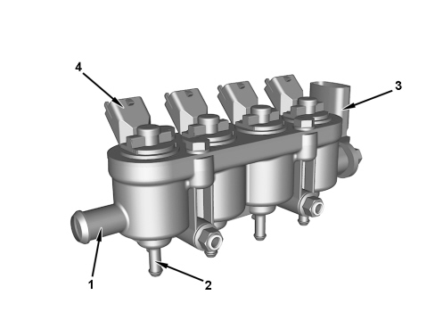
1. LPG inlet
2. LPG outlet
3. LPG temperature/pressure sensor
4. LPG injector connectors
LPG injectors meter LPG to be sent to the intake manifold.
The LPG injectors are supplied through signals from the petrol/LPG injector control SDU (Smart Driver Unit).
The LPG injector operating logic is sequential, timed type. That is, the injection is carried out individually in accordance with the single cylinder intake sequence.
LPG LEVEL SENSOR
The sensor is fitted directly on the tank and the signal, processed by the engine management control unit, allows the LPG level to be displayed on the instrument panel.
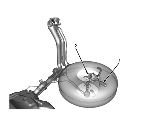
1. LPG level sensor float
2. LPG level sensor/gauge
LPG/PETROL SWITCH
The system features an LPG/petrol switch (1) located in the dashboard on the centre console near the DNA lever.
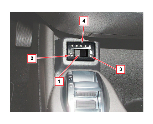
1. LPG/petrol switch
- the fuel in use is indicated by two LEDs (2) and (3);
- if pressed for 5 seconds with the key at MAR-ON, before starting, it allows start-up with gas (green LED (2) on constantly).
2. Green LED
- on constantly: indicates regular gas operation;
- flashing rapidly: it indicates the status of waiting for automatic switching to gas operation when starting (always on petrol);
- flashing slowly: it indicates a system malfunction during gas operation (diagnosis);
- on together with yellow LED: it indicates switching back to petrol. This mode is also signaled by the acoustic signal emitted by the switch.
3. Yellow LED
- on constantly: it indicates petrol operation.
4. Series of LEDs
- The green LEDs indicate the level of gas (divided into quarters) in the tank;
- the red LED indicates the reserve.