SPECIFICATIONS
Usually, when calibrating conventional shock absorbers a compromise is sought between the requirements of stability, safety and comfort.
The diagram below shows the typical response curves for traditional shock absorbers where it can be seen that the areas of stability and comfort are not interrupted as the calibration chosen is obviously determined by safety requirements.
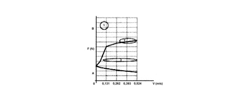
v. Shock absorber oscillation speed (body - wheel relative speed)
F. Shock absorber damping force
A. Compression
B. Rebound
1. Stability
2. Safety
3. Comfort
The damping control systems also provide the possibility of damping which is suitable for the conditions in which the vehicle finds itself; it is possible to alter the specifications of the shock absorbers between three different curves which can be achieved through the valves fitted on the shock absorbers, according to the style of the driver.
The diagram below illustrates the typical shock absorber response curves and the three different responses in terms of stability, safety and comfort can be seen.
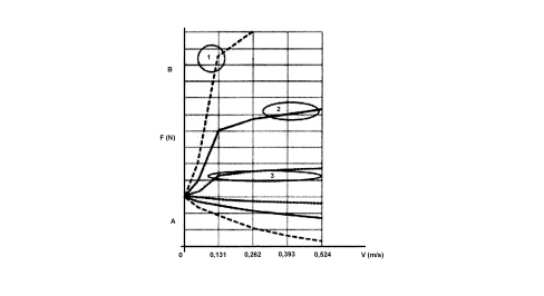
v. Shock absorber oscillation speed (body - wheel relative speed)
F. Shock absorber damping force
A. Compression
B. Rebound
1. Stability
2. Safety
3. Comfort
The RSS (Reactive Suspension System) designed for the Lancia Delta allows an enormous leap in terms of quality; through the intervention of proportional valves located in the shock absorbers, the system is capable of continuously altering the damping within a wide operating range as shown.
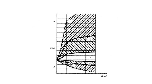
v. Shock absorber oscillation speed (body - wheel relative speed)
F. Shock absorber damping force
A. Compression
B. Extension
1. Stability
2. Safety
3. Comfort
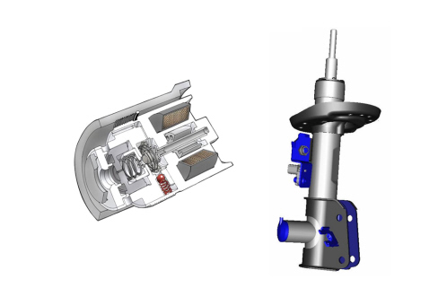
The proportional valves, illustrated in cross section in the figure below, can be operated, moment by moment, by a control unit which evaluates factors such as road conditions, motion of the vehicle and the reactions of the driver; within a few milliseconds, the control unit selects, independently for each wheel, the most suitable damping value for the conditions in which the vehicle finds itself, thereby maximising the driving comfort and the stability of the vehicle.
In this way the optimum damping selection made by the "RSS" system actively supports the driver in critical situations, significantly increasing safety and stability in addition to the pleasure of driving.
The damping action is varied by means of proportional valves governed by the control unit in rapid times; graphs A, B, and C in the figure below show the trends of the system response times in terms of request for intervention (A), times to generate the required current (B) and time to generate the required damping force (C).
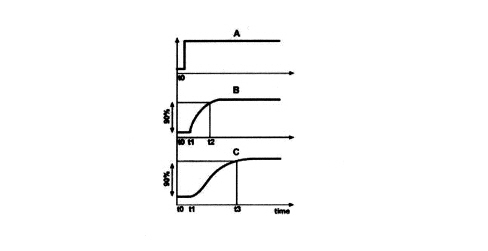
A - Intervention request
B. Current
C. Damping force
t1 - t0. delay time
t2 - t0. current generation time
t3 - t0. force generation time
GENERAL INFORMATION
The RSS (Reactive Suspension System) is capable of actively controlling the damping level of the suspension acting directly on each shock absorber.
The aim of the system is to improve control of vertical oscillations and the comfort and handling of the vehicle, acting on the vertical forces on the ground developed by each suspension, in particular differentiating between them individually according to the dynamic behaviour of the vehicle.
SYSTEM FUNCTIONS
The internal functions of the suspension damping control system are the following:
- function for recognising irregular surfaces;
- function for shock absorber control when holes/roughness are found;
- "sky-hook" function;
- function for lateral dynamic control;
- function for longitudinal dynamic control;
- function for damping control if the ABS is activated;
- function for damping control if the ASR is activated;
- function for damping control if the ESP is activated;
- function for controlling oversteer/understeer.
Function for recognising irregular surfaces
This function is based on the determination, by the control unit, of a road roughness index that takes into account the average value of acceleration on the wheel hubs, suitably dampened, compared to the car speed.
With this function, a high damping effect is obtained on irregular roads, with highly reduced body movement in all driving conditions.
Function for shock absorber control when holes/roughness are found
The control unit can detect the presence of a sudden hole in the road surface thanks to acceleration signals on the front wheel hubs, suitably dampened, and by the road roughness index.
Using an algorithm, it manages damping control to reduce impact on the rear axle and reduces swinging of the car body.
"sky-hook" function
The name "sky-hook" comes from the particular configuration of the theoretical suspension model on which the shock absorber management logic is based.
In the theoretical "sky-hook" model, the shock absorber, rather than being positioned parallel to the spring as in conventional models, is positioned in series with it and is connected to the chassis by a "dummy roof" which ideally follows the vehicle on its horizontal plane but is fixed along the Z axis.
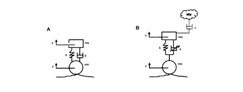
A. Conventional model
B. "Sky-hook" model
ms. Suspended mass
mn. Non-suspended mass
x. (Absolute) vertical movement of the suspended mass
y. (Absolute) vertical movement of the non-suspended mass
k. Spring flexible constant
d. Conventional shock absorber
e. Electronically-controlled shock absorber
c. "Sky-hook" effect
The fundamental difference compared with conventional operation consists in the fact that in the "sky-hook" model the relation of the shock absorber only depends on the movement of the chassis, whilst in the conventional model it depends on the relative chassis-wheel and body-wheel movement.
Obviously a system of this type cannot be produced in practice because the shock absorber cannot be physically positioned above the body; however, it is possible, managing the shock absorber according to a suitable logic, to confer "sky-hook" behaviour on a conventional suspension system.
The advantage of this design, compared with a conventional, passive shock absorber, consists in:
- less transmission of the stress inputs from the wheels (vibrations) to the body and therefore a decrease in the vertical accelerations which can be detected at the pedals and at the driver's seat in the passenger compartment;
- a decrease in roll (and roll speed) and in pitching during dynamic manoeuvres.
Function for lateral dynamic control
With this function, the car body roll is dramatically reduced.
According to the signals coming from the car speed, steering angle and lateral acceleration sensors, the control unit determines the correct damping to be applied on each proportional valve on the shock absorbers, to improve car control.
Function for longitudinal dynamic control
With this function, the car pitching while braking, accelerating and gearshifting is notably reduced.
According to the signals coming from the accelerator potentiometer, car speed, engine torque and brake pedal position sensors, determines the correct damping to distribute between the front and rear axles.
Damping control function if the abs - asr - esp are activated
If the ABS, the ASR or the ESP are activated, the control strategy imposes a shock absorber setting to improve and reduce braking distance, thanks to the perfect contact between wheel and ground, depending on the road roughness index.
Function for controlling oversteer/understeer
The system evaluates the oversteer/understeer coefficient based on the following signals:
- yaw sensor
- wheel speed
- lateral acceleration
- steering angle.
Using this information, it implements the control strategy to correct the distribution of the damping force between front/rear and left/right, to reduce understeer/oversteer conditions to a minimum, for an easier return to car safety conditions.
SYSTEM COMPOSITION
The system comprises:
- Three vertical accelerometers, located near the front domes and the rear left dome which measure the body vertical acceleration signals;
- two vertical accelerometers, located near the lower part of the front shock absorbers, which measure the wheel assembly vertical acceleration signals;
- DNA selector (manettino) to select the following operating modes NORMAL - DYNAMIC - ALL WEATHER;
- four variable calibration shock absorbers, controlled by solenoid valves;
- an electronic control unit.
Accelerations when cornering are detected by car sensors (yaw).
CONTROL STRATEGY
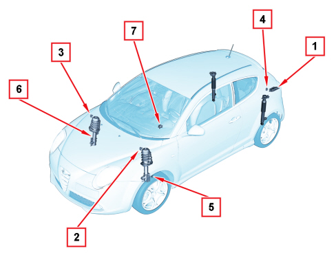
1. Control unit
2. Body acceleration (front left sensor)
3. Body acceleration (front right sensor)
4. Body acceleration (rear sensor)
5. Wheel acceleration (front left sensor)
6. Wheel acceleration (front right sensor)
7. DNA selector (manettino)
The system consists of five sensors capable, through numerical integration, of determining the relative speed among body, wheels and car dynamic; consequently it can select the optimum damping force that each shock absorber should provide; the instant detection by the sensors and the compression and extension adjustment guarantee that the damping forces produced at any moment contribute to braking the absolute vertical motion of the car, exactly as if the body were attached to the sky by a shock absorber.
"Sky-hook" principle
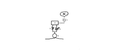
1. "Sky-hook" effect
2. Body
3. Spring
4. "Sky-hook" electronically-controlled shock absorber
5. Wheel
The control unit acquires the signals from the sensors and the CAN and after suitable filtering, controls and processing, calculates/measures:
- vertical speed of the four domes (the acceleration of the dome without a sensor is deduced on the basis of the three, considering the body as rigid);
- vertical speed of the four wheel hubs (the acceleration of the two rear hubs without a sensor is deduced on the basis of the acceleration of the two front domes, the wheelbase and the speed of the vehicle);
- relative vertical speed between hubs and body;
- delay time between front/rear axis;
- lateral acceleration;
- derivative of the lateral acceleration;
- longitudinal acceleration (derivative of the vehicle speed).
Then, according to the signals calculated/measured and some tuning parameter groups, it calculates the optimum value for the vertical force at each shock absorber.
Once these optimum vertical force values have been evaluated for the individual shock absorbers, the system identifies the current required, using an internal map, to supply each solenoid valve to produce the above mentioned vertical force.
At the same time it evaluates the maximum or minimum values for these supply currents for the solenoid valves and, when necessary, limits them.
The currents, calculated and filtered in this way, are sent to the solenoid valves to regulate the hardness of the shock absorber to the optimum value calculated previously.
Using the DNA selector (manettino) on the dashboard, the operating mode can be selected to optimise driving comfort or improve vehicle manoeuvring performance.
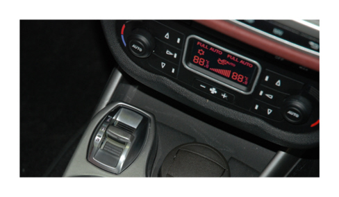
This system interacts with the DYNAMIC function: thus two driving settings can be selected, depending on the type of journey and on the road surface.
In “NORMAL” and “ALL WEATHER” operating mode, the active shock absorbers adjust the car suspension to suit the route type and the driving stresses, considerably improving driving comfort, in particular on rough terrain.
The "DYNAMIC" operating mode produces a sports driving setting featuring more responsive acceleration and greater effort on the steering wheel to give a sporty feeling. Furthermore, the shock absorber damping action is adjusted and divided to guarantee higher precision and reactiveness of the vehicle while maintaining a good comfort level.
The driver feels the vehicle cornering more precisely and a faster change in direction.
System failure and service interventions
RSS system failure
In the event of malfunction, the system notifies the driver by means of a dedicated message on the reconfigurable multifunction display instrument panel and by lighting the amber symbol, as shown in the following figure.

In case of failure/breakage of only one accelerometer, the system goes on operating using the signals from the other accelerometers - still working - and the failure warning light does not switch on.
If the control unit is replaced, the proxy alignment and calibration procedure must be carried out, using Examiner.
No procedure is required to replace one of the shock absorbers or accelerometers.
Electronic control of suspensions
Suspension is managed by a control unit located in the service compartment at the base of the windscreen, integrated with the car's C-CAN.
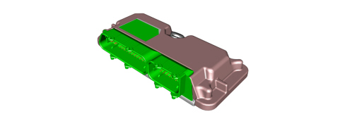
Control unit pin-out
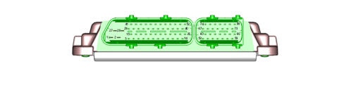
CONNECTOR A
Pin 1 - Earth RF
Pin 2 - Supply power earth
Pin 3 - Mode selection control earth
Pin 4 - Front left hub accelerometer sensor earth
Pin 5 - Front left chassis accelerometer sensor earth
Pin 7 - Front left chassis accelerometer sensor supply positive
Pin 8 - Front left hub accelerometer sensor supply positive
Pin 9 - C-CAN (high) line
Pin 10 - Front right chassis accelerometer sensor earth
Pin 11 - Front right hub accelerometer sensor earth
Pin 12 - Warning light earth
Pin 13 - Signal input
Pin 14 - Front left hub accelerometer sensor signal
Pin 27 - Permanent supply (+ 30) controlled by fuse
Pin 29 - Front right damper positive output
Pin 31 - Front left damper positive output
Pin 34 - Front right chassis accelerometer sensor supply positive
Pin 35 - C-CAN (low) line
Pin 36 - Ignition control input (+ 15) controlled by fuse
Pin 37 - Warning light positive
Pin 39 - Mode selection control signal
Pin 40 - Front right hub accelerometer sensor signal
Pin 42 - Front right damper negative output
Pin 43 - Front left damper negative output
Pin 44 - Signal input
Pin 45 - Front right hub accelerometer sensor supply positive
Pin 46 - C-CAN (high)
Pin 47 - C-CAN (low)
Pin 48 - K diagnosis
Pin 49 - C-CAN (low)
Pin 50 - C-CAN (high)
Pin 51 - Front left chassis accelerometer sensor signal
Pin 52 - Front right chassis accelerometer sensor signal
CONNECTOR B
Pin 54 - Rear left hub accelerometer sensor earth
Pin 55 - Rear right hub accelerometer sensor earth
Pin 56 - Rear right chassis accelerometer sensor earth
Pin 57 - Signal input
Pin 59 - Earth RF
Pin 67 - Rear right hub accelerometer sensor signal
Pin 68 - Rear left hub accelerometer sensor signal
Pin 69 - Rear right chassis accelerometer signal
Pin 70 - Rear right hub accelerometer sensor supply
Pin 71 - Rear right damper supply
Pin 72 - Positive control
Pin 73 - Rear left damper supply
Pin 75 - Signal input
Pin 76 - Rear left hub accelerometer sensor supply
Pin 77 - Rear right chassis accelerometer sensor supply
Pin 78 - Rear left damper negative output
Pin 79 - Rear right damper negative output
Pin 80 - Negative control