The dual fuel system comprises the basic petrol system (Magneti Marelli IAW 5SF3) and the LANDIRENZO OMEGAS PLUS system for LPG operation.
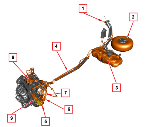
1. LPG filler
2. LPG cylinder
3. Petrol tank
4. LPG supply pipe (high pressure)
5. LPG pressure reduction unit
6. Cut out solenoid valve
7. LPG filter
8. LPG injector rail
9. LPG injection control unit
The basic engine control system is described in the subgroup 1056.
The timed sequential LANDIRENZO OMEGAS system is one of the latest petrol/gaseous LPG conversion systems.
The LPG control unit determines the gas injector injection times using the emulation impedance values of the gas ECU to acquire the petrol injection times during gas operation.
Engine control is carried out exclusively by the petrol control unit, while the LPG control unit converts all signals generated by the former, for petrol injectors, into suitable signals for the LPG injectors.
The LPG control unit acquires the petrol injection signals through the insertion of a harness connected to the control unit itself into the injector control line:
-
During petrol operation the LPG control unit's behaviour is totally transparent, allowing the petrol injectors to be controlled by the engine management control unit.
-
During LPG operation the OMEGAS control unit acquires the control signals for the petrol injectors generated by the petrol control unit and uses them as a calculation basis for managing LPG injection. The connection on the petrol injector line is interrupted and an impedance is generated which simulates that inside the injectors.
Thanks to this, the system does not significantly affect the original petrol one and can be effectively integrated with all its main (mixture strength control, cut-off, purge canister, cut-out for overrevolutions, etc...) and secondary functions (climate control system engagement control, electric loads, etc.).
Conversion from petrol injection to gas injection times is carried out according to a set of parameters acquired by the LPG control unit:
-
gas pressure in rail;
-
gas temperature;
-
engine coolant temperature
-
engine rpm
-
battery voltage.
To obtain a perfect consistency with the petrol system, the LPG control unit injects gas into the same cylinder where the injection time for petrol has been acquired.
OPERATION
In both system operation modes, petrol and LPG, the corresponding control units are always supplied during engine operation.
Usually the vehicle is started on petrol and for emergency situations, the LPG starting option is available as well and can be selected by the switch. After starting, if the switch is in gas position, the LPG control unit checks whether the conditions for switching are met.
The liquid gas, stored in the tank at a pressure which depends on the mixture composition and environmental temperature, is atomised in the pressure reduction unit and adjusted to an outlet pressure 0.95 bar higher than the vacuum in the intake manifolds.
As soon as following conditions are reached:
-
idle threshold,
-
engine coolant minimum temperature threshold (signal shared with the petrol control unit),
-
acceleration when exceeding 1400 rpm,
the solenoid valves open and, after 1 second, the system switches to LPG.
At this point the petrol injectors are deactivated and the LPG control unit starts operating the LPG injectors.
Thus, the injectors supply the correct quantity of gas that is sent to the intake manifold, timed for each cylinder.
The gas injection map is calibrated in order to make a specific adaptation for gas operation unnecessary so that the adaptation managed by the petrol control unit can be used.
In addition to gas injector management, the LPG control unit also controls other functions of the LPG system, for example the fuel level indication, solenoid valve control, switching back to petrol if the LPG runs out, petrol pump deactivation, etc.
Diagram showing information entering/leaving the control unit
Input signals
Petrol injector opening time
The system uses the petrol injection times as the main parameters for calculating the quantity of LPG to be injected: the LPG control unit converts the petrol injection times into specific LPG injection times and applies them during injector control.
The voltage supplied to the petrol injectors is also used for key-on condition recognition.
Engine speed signal
The engine rpm signal is one of the two basic parameters, together with petrol injection time, used to convert petrol injection time into gas injection time.
It is also used to check whether the engine is operating or not.
Coolant temperature signal
The coolant temperature is used:
-
- to manage petrol - LPG switching;
-
- to correct LPG injection time.
This correction is used to manage engine warm-up during LPG operation.
Gas temperature signal
Gas temperature is used to correct gas injection time; this correction compensates for density and volume energy changes during engine operation, as temperature changes.
Gas pressure signal
As pressure increases, LPG density and volume energy increase as well. To compensate for this, the control unit corrects LPG injector opening time.
The gas pressure signal is used also to determine when switching back to petrol is required, if the LPG tank is empty or if the LPG filter is blocked.
Lpg level sensor
The LPG level sensor on the multivalve stack informs the control unit about the quantity of LPG in the tank. The control unit uses this signal to inform the user, showing the fuel level gauge in the petrol/LPG operation switch.
It is also used to inform the user if problems occur, if diagnosis has triggered or if switching back to petrol has been activated.
Output signals
Lpg injector opening time control
The LPG control unit determines the LPG injector injection times, calculated by correcting the petrol injector opening times.
Lpg solenoid valve control
The LPG control unit operates the two solenoid valves in the system:
-
multivalve stack on the tank
-
pressure reduction unit/vaporiser.
Gauge/switch
The switch/gauge shows:
-
the type of used fuel;
-
the quantity of LPG in the tank;
-
diagnosis signals and buzzer.
Pump operation and petrol injector exclusion
During LPG operation the OMEGAS control unit interrupts the supply to the petrol pump and inhibits petrol injector operation.
OMEGAS PLUS INJECTION CONTROL UNIT
The control unit is fitted under the front bumper, in front of the front left wheel, and is capable of withstanding high temperatures.
It is a digital unit with a microprocessor and is characterised by high processing capability, precision, reliability, versatility, low power consumption and zero maintenance.
The task of the electronic control unit is to process the signals from:
-
additional sensors belonging to the LPG system,
-
signal from the engine coolant temperature sensor, shared with the petrol system,
-
signals from the petrol control unit concerning petrol injector control,
and, applying specific maps, to control the operation of the actuators (in particular the LPG injectors and LPG cut out solenoid valves) in order to ensure the optimum operation of the engine.
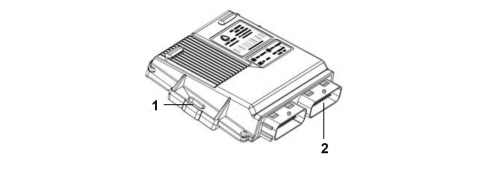
- 1, Omegas Plus control unit
- 2, Connector
Omegas plus control unit pin-out
The following diagram shows the control unit pin-out.
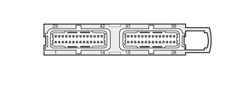
- 1, Petrol injector 1 cut-out, control unit side
- 2, Petrol injector 2 cut-out, control unit side
- 3, Petrol injector 3 cut-out, control unit side
- 4, Petrol injector 4 cut-out, control unit side
- 5, Ignition-operated 12 V
- 6, Gas temperature signal
- 7, N.C.
- 8, Gas pressure signal
- 9, Pressure sensor 5 V supply
- 10, Serial RX
- 11, Serial supply
- 12, N.C.
- 13, N.C.
- 14, N.C.
- 15, 12 V battery
- 16. N.C.
- 17, N.C.
- 18, LPG level sensor signal
- 19, N.C.
- 20, K line
- 21, LPG level sensor earth
- 22, Logic earth
- 23, Petrol pump relay control
- 24, Gas solenoid valve control
- 25, Power earth
- 26, Positive for gas injectors 1 and 2
- 27, Gas injector 1 control
- 28, Gas injector 2 control
- 29, Petrol injector 1 control (injector side)
- 30, Petrol injector 2 control (injector side)
- 31, Petrol injector 3 control (injector side)
- 32, Petrol injector 4 control (injector side)
- 33, Engine coolant temperature signal
- 34, N.C.
- 35, N.C.
- 36, Turbo pressure
- 37, Pressure sensor earth
- 38, Serial TX
- 39, Serial L GND
- 40, N.C.
- 41, N.C.
- 42, Rpm signal
- 43, 12 V battery
- 44, N.C.
- 45, N.C.
- 46, N.C.
- 47, Serial switch
- 48, Switch
- 49, Switch supply
- 50, Switch earth
- 51, N.C.
- 52, Gas solenoid valve earth
- 53, Power earth
- 54, Positive for gas injectors 3 and 4
- 55, Gas injector 3
- 56, Gas injector 4
LPG INJECTOR RAIL
Fitted with special bracket on cylinder head extension as shown in the picture.
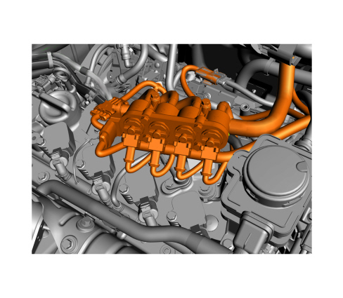
The LPG coming from the filter enters the connector (1) and supplies the injectors.
The gas is suitably metered and flows out of the injectors through the outlets (2) and reaches the intake manifold, and therefore the engine, through special hoses.
The injectors are controlled by the OMEGAS control unit and linked to the unit by connectors (4).
The pressure and temperature of the gas in the rail are measured by the sensor (3).
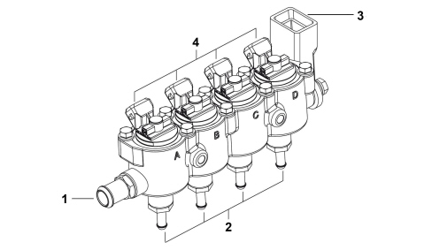
- 1, Gas inlet
- 2, Gas outlet
- 3, Gas pressure/temperature sensor
- 4, Wiring harness connector
LPG INJECTORS
The injectors on the rail meter the gas to be sent to the intake manifold.
The LPG injectors are supplied through signals from the LPG control unit.
The injector operating logic is sequential, timed type. That is, the injection is carried out individually in accordance with the single cylinder intake sequence.
LPG/PETROL SWITCH
The switch is located in the tunnel cover and has a double function: it allows the selection of petrol or LPG operation and shows the level of LPG in the corresponding tank.
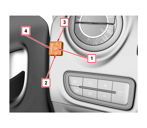
1, Gas/petrol button
-
the fuel in use is indicated by two LEDs (2) and (3);
-
if pressed for 5 seconds with the key on MAR, before starting, it allows start-up with gas (green LED 2 on constantly).
2, Green LED
-
constantly lit: it indicates regular gas operation;
-
rapid flashing: it indicates the status of waiting for automatic switching to gas operation when starting (always in petrol);
-
slow flashing: it indicates a system malfunction during gas operation (diagnosis);
-
on together with yellow LED: it indicates switching back to petrol. This mode is also signaled by the acoustic signal emitted by the switch.
3, Yellow LED
-
constantly lit: it indicates petrol operation.
4, LED series
-
The green LEDs indicate the level of gas (divided into quarters) in the tank;
-
the red LED signals the reserve.
Switching from one fuel type to the other
It is advisable to switch from one fuel to the other with the engine off or, with the vehicle moving, if the engine is running.
From petrol to gas
Press button (1); the switch to LPG will take place automatically at the first significant acceleration. At the same time the fuel level gauge (4) activates, the yellow LED (3) switches off and gas supply is signaled by the green LED (B) which switches from rapid intermittent operation to constantly lit.
From gas to petrol
Remove your foot from the accelerator and press button (1). Petrol operation is signaled by the yellow LED (3) switching on. If the LPG runs out, the system automatically switches back to petrol, informing the user by means of:
-
green LED (2) and yellow LED (3) coming on at the same time;
-
acoustic signal emitted by the switch
SYSTEM SELF-DIAGNOSIS
The LPG injection system self-diagnosis indicates LPG operation and possible malfunctioning or incorrect data acquisition by means of the green LED (2).
When one of these faulty conditions occurs, the green LED starts flashing slowly during gas operation.
In the event of faults that could affect the correct operation of the engine, the control unit will automatically switch from gas operation to petrol operation.
This condition is signalled by the switching on of the yellow LED, by the slow flashing of the green LED and by the switch's buzzer.