ON BOARD INSTRUMENTS
Introduction
The instruments are designed to provide a family feeling with other models of the same make characterised by red graphics, gauge and display.
A sports version with white graphic light is forthcoming.
The panel is installed behind the steering wheel.
Its position guarantees maximum visibility/legibility of the information for the driver in all vehicle usage conditions (day/night) without reflections, distortions or double images.
A “welcome movement” can be adopted: the gauges are operated at key-on with a guided warning light and display animation procedure.
Gauges
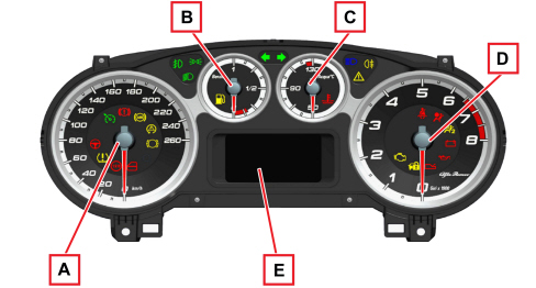
The instrument panel is installed behind the steering wheel. It is connected to the CAN and includes 4 gauges produced using stepper motors.
PETROL ENGINE VERSIONS
DIESEL ENGINE VERSIONS
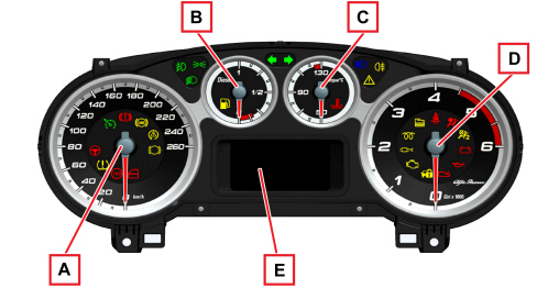
A - Electronic speedometer
B - Fuel level (with insufficient fuel level warning light)
C - Engine coolant temperature gauge (with overheating warning light)
D - Electronic rev counter
E - Display (available in two different versions)
Warning lights
There are also numerous LED negative contrast warning lights (there is also setups for warning lights that can be activated in discrete mode and/or by the CAN).
Buzzer
The instrument contains a buzzer with 8 different settings to carry out the following functions:
- alarm/warning/danger signals
- Signalling requested by TCT automatic transmission (where present)
- parking sensor signals (where fitted)
- Seat Belt Reminder
- direction indicators/hazard warning lights acoustic signals
- push button roger beep
- Start&Stop signalling
The acoustic signals can vary in intensity and frequency depending on the function signalled.
The volume for the alarm signals can be adjusted down to zero (signal excluded) except for the seat belt reminder and direction indicator/hazard warning light signals which is fixed or the automatic transmission and the parking sensor which has a minimum volume that is not zero.
Buttons
The instrument is connected to 3 buttons on the left side of the dashboard for the management of the fog light, the rear fog light, the headlamp alignment correction, the dimming and the Setup menu (buttons "MENU/ESC", "+", "-").
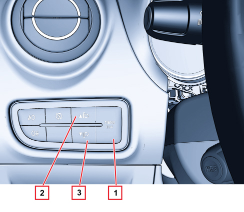
1 - “MENU/ESC” button
2,3 - "+" and "-" buttons
“MENU/ESC” button:
- pressing it briefly allows the activation of the set up (illustrated below) and confirms it and memorizes the settings
- pressing it for longer produces the return to the standard screen
"+" and "-" buttons:
- allow the setting of the correct headlamp alignment outside the setup menu
- allow the selection, setting and adjustment of the functions in the setup menu
The dimming is managed by an item in the setup menu.
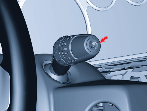
The "TRIP" function is managed by the special button in the stalk unit.
Display
The control panel display is available in two versions depending on the vehicle's on-board technological specifications:
- MATRIX type display
- COMFORT type display
Matrix type display
Example: standard page at Key ON with dipped headlamps on.
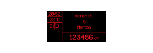
This is a red negative transmissive reconfigurable matrix STN display with a two colour zone (red/amber) dedicated to the display of symbols summarizing the displays (zone G).
The visible area of the reconfigurable matrix display is 67-mm wide and 35-mm high with a resolution of 172 x 90 pixels and is divided into zones as illustrated in the diagram below:
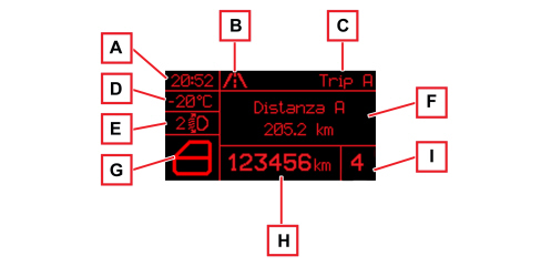
A time
B identification symbol for function displayed
C displayed function heading
D outside temperature
E headlamp alignment corrector
F area for displaying messages / information / settings, etc.
G area for displaying summary symbol
H total odometer
I gearshifting indications
The Audio Repetition, Trip and Menu messages are displayed in zone F.
The headings and symbols are displayed in the status bar (zone B + C).
The fault / information messages and the date are displayed in zone B + C + F.
Displays at the Key OFF
A short animated sequence appears on the display at key-off:
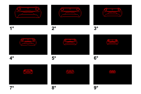
At key-off and when a front door is opened, the display shows the clock, the external temperature and total odometer.
Another short animated sequence will appear at key-off and when a front door is closed:
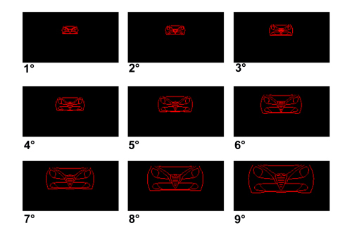
During the above described animation, all gauges on the panel will run two short pulsing light cycles.
Comfort type display
Example: standard page at Key ON with dipped headlamps on.
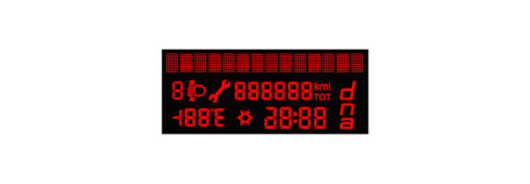
It is a negative transmissive three-line alphanumerical STN type display.
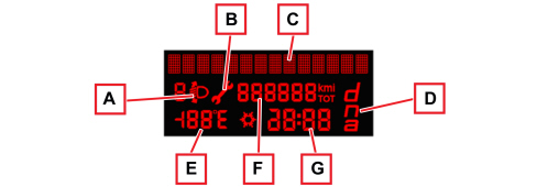
The top line, with 14 dot matrix characters (7x5) (C) is for displaying:
- Date
- Trip computer data (processed by the control panel)
- Set-up menu with messages for settings/adjustments
- Messages about: activation of functions/service/faults/information/feedback
- Repetition of Audio / Telephone function readings
- User interface from Blue&Me
The two bottom lines in segments are for displaying:
- Total odometer (F)
- Clock (G)
- Outside temperature and snow symbol (ice danger) (E)
- Headlamp alignment corrector reading (A)
- DNA system mode (D)
- Service symbol (spanner) (B)
Versions with Start&Stop
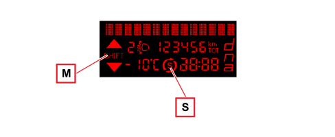
When the engine is stopped by the Start&Stop function, this is signalled by the S icon; in addition the "gear shift indication" M appears on the left.
Displays at key-off and key-on
At key-off and when a front door is opened/closed, the display shows the clock, the external temperature and total odometer.

Key-on with welcome movement
At every key-on a check is launched for all the electronic control units present on board the vehicle with some of the warning lights in the panel coming on. At the same time, the panel operates the tachometer and rev counter dials will be operated for the entire scale (welcome movement). Graphics and display activation will be delayed until the end of the movement with fade effect.
Warning lights
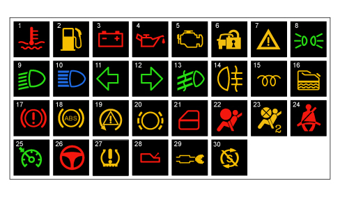
1 - Engine coolant max. temperature
2 - Fuel reserve
3 - Alternator failure
4 - Minimum engine oil pressure
5 - EOBD and engine management system failure
6 - Vehicle protection system failure
7 - General failure
8 - Side lights
9 - Dipped headlamps
10 - Main beam headlamps
11 - Left direction indicator
12 - Right direction indicator
13 - Fog lights
14 - Rear fog lamps
15 - Heater plugs (JTD)
16 - Water in diesel filter sensor (JTD)
17 - Handbrake applied / insufficient brake fluid level / EBD failure
18 - ABS failure
19 - ESP system intervention / failure
20 - Brake pad wear
21 - Doors open warning
22 - Air Bag failure
23 - Passenger Air Bag disablement
24 - Seat belts not fastened
25 - Cruise control on
26 - Electric steering failure
27 - Insufficient tyre inflation pressure
28 - TCT automatic transmission fault
29 - Pollution filter blocked (JTD)
30 - Start&Stop device deactivated
Additional symbols in matrix display:
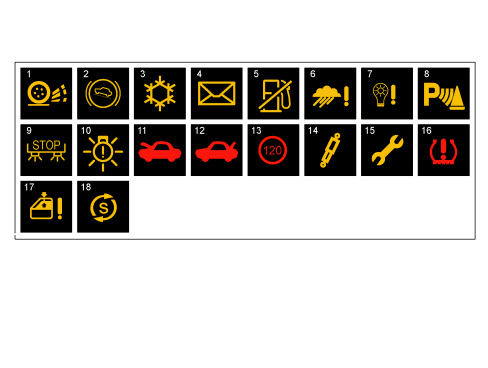
1 - ASR system off
2 - Hill Holder failure
3 - Possible ice on the road
4 - Incoming SMS message warning
5 - Inertia switch / Fire Prevention System intervention
6 - Rain sensor failure
7 - Dusk sensor failure
8 - Parking assistance system failure
9 - Brake lights failure
10 - Exterior lights failure
11 - Bonnet open
12 - Tailgate open
13 - Speed limit exceeded
14 - Controlled suspension system
15 - Service function
16 - Insufficient tyre inflation pressure
17 - Anti-pinch function not available
18 - Start&Stop device activated

|
The "General Failure" warning light summarizes the following signals for the Comfort panel: - Fire Prevention System activated - Rain sensor failure - Dusk sensor failure - Parking assistance system not available - Anti-pinch system not available - Engine oil pressure sensor failure - Automatic transmission safety signals - Exterior lights failure - Start&Stop failure |
|
|
The "General Failure" warning light summarizes the following signals for the Matrix panel: - Engine oil pressure sensor failure - Automatic transmission safety signals |
Connector pin out
The instrument panel (18-way) connector is illustrated below.
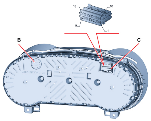
B - buzzer
C- connector
|
PIN |
FUNCTION |
|
1 |
Earth |
|
2 |
+battery power supply from F53 |
|
3 |
+ignition power supply from F37 |
|
4 |
Belt display connection LIN line |
|
5 |
B-CAN A (low) |
|
6 |
B-CAN B (high) |
|
7 |
Headlight corrector actuator control |
|
8 |
Dipped headlamps power supply from F13/T01 |
|
9 |
Negative signal from trip button on steering column switch unit |
|
10 |
Warning light power supply setup (n.c.) |
|
11 |
Engine oil level sensor (signal) (n.c.) |
|
12 |
Engine oil level sensor (earth reference) (n.c.) |
|
13 |
Negative signal from MENU control and from control + |
|
14 |
Negative signal from headlamp alignment corrector controls |
|
15 |
Negative signal for buzzer operation (n.c.) |
|
16 |
Negative signal from control - |
|
17 |
Warning light negative control setup (n.c.) |
|
18 |
Warning light negative control setup (n.c.) |
Gauges
Speedometer
The instrument panel increases the actual speed value slightly (6% + 1 km/h but this increase also depends on the tyres fitted on the vehicle) for safety reasons, and never exceeds the maximum tolerance prescribed in the directives of the countries where the vehicle is sold.
The increase is calculated according to the panel.
At the key-on the gauge is at 0 (zero) km/h (or mph) and the instrument panel then displays the vehicle speed information.
Rev counter
At the key-on the gauge is at 0 (zero) RPM and the instrument panel then displays the engine rpm information.
There is also a logic to prevent fluctuations of the rev counter with the engine idling.
Fuel level gauge
2 seconds after the key-on the gauge shows the fuel level information.
The reading at the start of the "fuel reserve" is red and the warning light is an amber LED in the gauge graphics. The calibration of the gauge ensures maximum precision at the start of the red sector.
Engine coolant temperature gauge
2 seconds after the key-on the gauge shows the engine coolant temperature information.
The reading at the start of the "danger zone" is red and the warning light is a red LED in the gauge graphics. The calibration of the gauge ensures maximum precision at the start of the red sector.
Behaviour of the gauge:
- If the temperature is below 50°C the gauge is at the first reference on the scale.
- For temperatures between 50 and 80°C the gauge moves in a linear fashion.
- For temperatures between 80 and 115°C (normal operation), the pointer remains in a stable position in the centre of the scale.
- For temperatures between 115 and 124°C (and rising) and between 120 and 115°C (and decreasing) the pointer moves in a linear fashion between the centre of the scale and the start of the red danger sector (124 - 130°C).
- For temperatures of 124°C (and rising) the pointer remains at the start of the red danger zone on the scale.
Main functions
The main features are summarized in the table below.
|
CONTENT |
COMFORT PANEL |
PANEL MATRIX |
|
Fuel level and reserve indicator |
X |
X |
|
Headlight alignment corrector |
X |
X |
|
Hot engine coolant temperature and overheating indicator |
X |
X |
|
Rev counter |
- |
X |
|
Minimum engine oil pressure indicator |
X |
X |
|
Speedometer |
X |
X |
|
EOBD reading |
X |
X |
|
Odometer and trip meter reading |
X |
X |
|
Plug preheating and failure indicator |
X |
X |
|
Cruise Control state indicator |
X |
X |
|
Rear and front fog light state indicator |
X |
X |
|
Rear and front fog light state indicator |
X |
X |
|
Light dimming management |
X |
X |
|
Direction light state indicator |
X |
X |
|
Brake light failure indicator |
X |
X |
|
Door/tailgate/bonnet state indicator and buzzer with vehicle in movement |
X |
X |
|
Tyre state indicator (TPMS) |
X |
X |
|
Brake pad wear state indicator |
X |
X |
|
Airbag failure indicator |
X |
X |
|
Front seat belt state indicator (SBR) |
X |
X |
|
Front and rear seat belt state indicator control (SBR) |
X |
X |
|
Speed limit indicator (customisable in menu) |
X |
X |
|
Speed limit indicator (some countries) |
X |
X |
|
Passenger airbag status with status management from setup menu |
X |
X |
|
Handbrake applied indicator |
X |
X |
|
Low brake fluid level indicator |
X |
X |
|
Rain sensor failure indicator |
X |
X |
|
Repetition of audio information from radio |
X |
X |
|
Repetition of audio information from radio navigator |
X |
X |
|
Time and data management and indication |
X |
X |
|
Trip Computer |
X |
X |
|
Repetition of navigation information from Blue&Me |
- |
X |
|
Repetition of navigation information from map radio navigator |
- |
X |
|
Parking sensor signal management |
X |
X |
|
Outside temperature and ice danger indicator |
X |
X |
|
Automatic transmission indications management |
- |
X |
|
Display heater setup for versions with automatic transmission |
- |
X |
|
Setup menu management and display |
X |
X |
|
Power steering failure indicator |
X |
X |
|
External light state and failure indicators |
X |
X |
|
Water in diesel filter sensor indicator |
X |
X |
|
Scheduled service management and display |
X |
X |
|
Particulate filter state indicator |
X |
X |
|
VPS system indicators |
X |
X |
|
Braking system with ABS indicators |
X |
X |
|
Braking system with ESP indicators |
X |
X |
|
Degraded oil function indicators |
X |
X |
|
Fuel switch tripped indicators (FPS) |
X |
X |
|
DST failure indicator |
X |
X |
|
Vehicle dynamics selector state indicator (DNA) |
X |
X |
|
Suspension system failure indicator |
X |
X |
|
Bluetooth displays |
X |
X |
|
Buzzer management |
X |
X |
|
Turbo pressure indicator |
- |
X |
|
Logistic Mode - Power Supply management |
X |
X |
|
Start&Stop device |
X |
X |
|
Welcome movement |
X |
X |
|
Car Configuration and Check-PROXI |
X |
X |
Lighting
The lighting for the Comfort display is activated at the key-on and dimmed at night (night mode); the lighting for the Matrix display is activated and dimmed at the key-on (day mode and night mode).
The lighting of the graphics and the pointers, on the other hand, is activated and dimmed at night (night mode).
If there are failure messages (except for "Ice danger" and feedback messages), the brightness of the display is automatically set at the maximum daytime value even in night time conditions.
Brightness sensor (some versions only)
The control panels with bright graphics have a brightness sensor to manage the vehicle on board lighting appropriately. The brightness sensor is incorporated in the control panel.
The control panel distinguishes daytime (day mode) from night time (night mode) conditions depending on the status of the side lights (activated / deactivated) and the sensor signalling.
If there is no sensor (versions with dark graphics) the control panel distinguishes daytime from night time conditions depending on the side lights status only.
Dimming
For the Comfort panel in daytime conditions (day mode), the display is lit to 100% and the brightness cannot be adjusted (dimmed). The adjustment is only possible in night time conditions (night mode).
The brightness of the display can be adjusted (dimmed) for the Matrix panel in daytime conditions as well.
In night time conditions, the brightness of the display is automatically dimmed to a pre-set level and the graphics and the pointers light up. The driver can adjust the brightness of the panel, the radio, the RadioNav and the automatic climate control (to 8 settings) via an item in the setup menu.
The lighting brightness cannot be reduced to zero.
If the brightness is adjusted the display shows the specific message and the brightness adjustment symbols come on/go off. With all the symbols lit up, the brightness is at the maximum level.
The effect of the adjustment is immediately visible.

Set-up menu
The set up menu functions can only be activated with the vehicle stationary except for the following functions: "Dimming" and "Speed limit" (selecting activation/deactivation of speed limit and selecting speed limit level).
By pressing the MENU ESC, + and - buttons in the left control panel it is possible to carry out the various operations of selecting/adjusting/setting the data displayed. The standard screen is restored after 1 minute if nothing is done.
Initial setting - instrument initialization
The table below shows the settings that can be adjusted using the set up menu and the value entered during production at the end of the line which the customer will find when they purchase the vehicle.
|
Feature |
Default value |
|
Dimming |
6 |
|
Speed limit (On/Off) |
OFF |
|
Speed limit (level) |
130 km/h |
|
Dusk sensor setting (1...3) |
2 |
|
Rain sensor setting (1...4) |
1 |
|
Trip B (On/Off) |
ON |
|
Clock adjustment (hh/mm) |
0:00 |
|
Time mode (12h/24h) |
24h |
|
Date adjustment (dd/mm/yyyy) |
01/01/yyyy (yyyy: SW release year) |
|
First page (partial distance or date) |
Partial distance |
|
Audio info repetition (On/Off) |
OFF |
|
Doors/boot locking with speed >20 km/h (On/Off) |
OFF |
|
Door opening function |
Opens all |
|
Distance unit of measurement (km/mi) |
km if speedometer scale is in km mi if speedometer scale is in mi |
|
Consumption unit of measurement (km/l, l/100 km, mpg) |
l/100 km if the speedometer scale is in km mpg if the speedometer scale is in mi |
|
Temperature unit of measurement (°C / °F) |
°C |
|
Language |
Italian |
|
Buzzer volume (0...7) |
4 |
|
Button volume (0...7) |
4 |
|
Seat Belt Reminder reactivation (item only present if SBR is deactivated) |
--- |
|
Service (km or mi) |
km if speedometer scale is in km mi if speedometer scale is in mi |
|
Passenger air bag activation/deactivation |
Depending on the signals received from the Air Bag Node Confirm: always NO |
|
Daylight lights (DRL) activation/deactivation. |
ON |
|
Courtesy lights activation/deactivation |
Trip computer
The Trip Computer shows vehicle trip, fuel consumption and mileage details on the control panel display.
There are two Trip Computer modes (A and B) which are completely independent; the display can be activated by pressing the TRIP button on the right steering column switch unit lever.
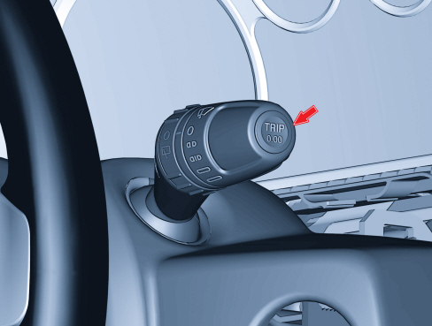
The button on the right lever with key-on displays the readings described below and allows to reset them before starting a new journey:
– short press: values display;
- long press: reset readings and start a new mission.
The data display mode follows a preset order:
Trip a:
- Range
- Distance travelled
- Average fuel consumption
- Instant fuel consumption
- Average speed
- Journey time
Trip b:
- Distance travelled - B
- Average consumption - B
- Average speed - B
- Journey time - B
Trip computer parameters
The measurements displayed can be expressed according to the Decimal Metric System (km, km/h, km/l, l/100 km) or the Imperial System (mi, mph, mpg) as selected by the driver (see set-up menu).
The Trip Computer is reset:
- manually by the user by pressing the "TRIP" button for a prolonged period;
- automatically when the distance travelled reaches 9999.9 km (miles) or when the journey time reaches 99:59 (99 hours and 59 minutes).
- every time the battery is reconnected.
A descriptive text (title) appears for 2 seconds on the matrix display when the trip readings are displayed by pressing the corresponding button.The title is then replaced by an icon:
the “autonomy” reading in the example shown
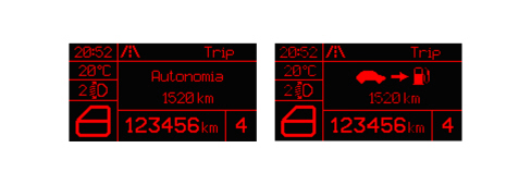
Trip Exit:
The TRIP function is automatically exited once all the measurements are displayed or by pressing the SET button for more than 2 seconds.
Trip Computer parameters:
Range [km] or [miles]: this indicates the estimated distance that can be travelled with the fuel currently in the tank based on the same style of driving being maintained.
Distance travelled [km] or [miles]: indicates the distance travelled by the vehicle from the "start of the journey", i.e. when the driver reset the equipment. The reading is consistent with the display on the total mileage recorder. The display is updated every 0.1 km.
Average fuel consumption [km/l] or [l/100 km] or [mpg]: indicates the average consumption from the start of the journey.
Instant fuel consumption [km/l] or [l/100 km] or [mpg]: indicates the constantly updated fuel consumption. This makes the driver aware of differences in fuel consumption linked to driving styles.
Average speed [km/h] or [mph] : is calculated from the start of the journey.
Journey time [hh:mm]: indicates the time elapsed since the start of the journey between 0:00 and 99:59 with a resolution and updating of 1 minute. When the maximum possible value is reached, the counting is automatically zeroed.
Programmed maintenance signalling (service)
When the programmed maintenance (service) is close, the message "Service" and the "Spanner" symbol are automatically displayed at the key-on (after the initial check procedure) followed by the number of kilometres (or miles) until the next service is due.
The information shown on the display can also be requested by the user by selecting a special item in the set-up menu, irrespective of the interval: the kilometres (or miles) remaining are shown on the display. In this case the "Spanner" symbol does not appear.
The Planned Maintenance programme includes 6 services at intervals of 30000 km (or 18000 miles).
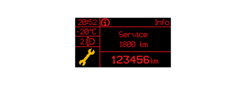
Automatic display:
The first message is automatically displayed once only at the key-on if the number of kilometres (or miles) until the next service is 2000 km or less or the equivalent in miles.
Later on, the message is only displayed once at the key on at the following partial levels: 1800, 1600, 1400, 1200, 1000, 800, 600, 400, 200, 100, 50 km or the equivalent figures in miles and they are not displayed during the intervening period.
When the limit is reached (0 km/mi) the message is displayed at every key on for the next 1000 km after which it no longer appears.
The display can be interrupted by pressing the "MODE" button.
Display on request:
The interval can be displayed on request any time by means of a specific item in the set up menu.
Display after the 6 services.
Once all 6 services are over no message is displayed automatically and the relevant item can no longer be selected from the set up menu (it is no longer activated).

|
Reset At each service interval, the Service personnel should: - reset the km (or miles) counter to the starting value using the diagnosis equipment; - record that the Service has been carried out; a record of the last service carried out should remain with details of: service date/ service no. carried out / total mileage. This information is preserved in the memory even if the vehicle battery is disconnected. |
|
|
Control panel replacement If the control panel is being replaced, the Service personnel should: - reset the km/mi in the odometer; - read the number of services carried out and enter them into the new control panel; - read the km/mi until next service counter and enter information into the new control panel; - read the last service date and rewrite it in the new control panel. |
|
|
The PROXI alignment must always be carried out when the control panel is replaced. If the alignment is not carried out, the odometer flashes and the control panel does not work. |
Fault diagnosis
The diagnosis of the instrument panel can be carried out using the diagnosis equipment available in the network (Examiner or Examiner plus).
The diagnosis socket is located in the EOBD, the line used is the B-CAN line.
The following operations are included in the diagnosis:
- display of possible errors present in the instrument panel
- alignment of the PROXI with the B-CAN (memorizing of specific vehicle parameters), if the instrument panel is being replaced
- memorizing the odometer mileage
- setting the mileage for the SERVICE function
- carrying out the active diagnosis in order to check the operation of the instrument panel.
Gear display (tct transmission)
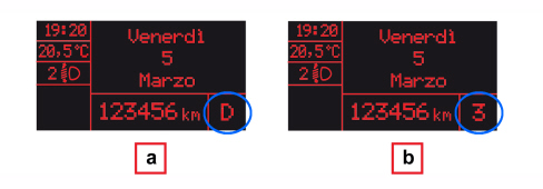
On versions with TCT automatic transmission the display shows the gear engaged:
- in automatic driving mode, the gear selected (P, R, N, D), fig. a;
- in sequential driving mode the manual engagement of a higher or lower gear, respectively, with the relevant number, fig. b.
Gear shifting display (manual gearbox)
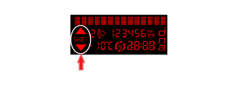
In combination with the Start&Stop device, the display shows three "gearshifting suggestion" icons on all versions with manual gearbox.
The gearshifting indication advises the driver to change gear (higher ratio: shift up or lower ratio: shift down) using a suitable indication on the control panel.
This gearshifting suggestion is designed to improve fuel consumption and driving style.
|
|
The gearshifting indication on the instrument panel remains on until the driver changes gear, or until the driving conditions change and no gear change is required to improve consumption. |
When requested by the engine management control unit, the Body Computer indicates the suggestion to "shift up" or "shift down", or gives no suggestion (icons switched off).
Turbo pressure display (for matrix panel only)
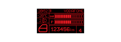
When enabled and where the engine is turbocharged, the (standard sports screen) display appears after the check stage at the key-on (5 seconds.) as an alternative to the date.
The display of the turbo pressure or the date can be selected using a specific item in the vehicle setup menu.
Warning light for particulate filter (jtd engines only)
The system that manages the operation of the particle filter has three warning lights in the instrument panel for signalling the accumulation status of the actual filter.
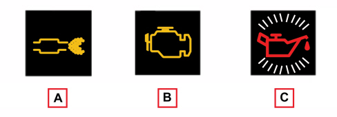
The "filter blocked" warning light (A) is activated after a certain number of "unsuccessful" regenerations, i.e. if the driving behaviour at that moment does not allow the automatic activation of the regeneration procedure or this operation has not been successfully concluded due to another problem.
It is advisable to keep the car running for a while to try and carry out the regeneration, otherwise, if the warning light remains on, it is indispensable to carry out the forced regeneration using the diagnosis equipment (Examiner):
Op. 0520G12 PARTICULATE FILTER (D.P.F.) - REGENERATION EXAMINER
With the warning light (A) on, the EOBD warning light (B) also comes on if the filter conditions worsen (the accumulation level of 250% is exceeded) so that the smooth operation and condition of the exhaust system is put at risk. In this case it is vital to carry out the forced regeneration using the diagnostic equipment (Examiner):
Op. 0520G12 PARTICULATE FILTER (D.P.F.) - REGENERATION EXAMINER
The warning light (B) comes on even with the warning light (A) off, if errors have been detected, e.g. relating to the DPF system sensors: in this case, use the diagnosis equipment for all cases of the EOBD warning light coming on.
During the filter regeneration stage, the particulate being "washed" may pollute the engine oil.
For this reason, the "minimum engine oil pressure" warning light is also used on engines with a DPF filter that flashes together with the message "Change the engine oil" in the display when the system detects that the engine oil has deteriorated to a certain extent, requesting an oil change in advance of the scheduled one (managed by the control panel - "Service" function). The extent of the deterioration of the oil is not measured by a dedicated sensor, but calculated by an algorithm in the engine management control unit depending on: the number of DPF regenerations, kilometres covered (mileage), number of engine starting cycles, number of cold starts, oil temperature average value, etc.
The warning light turns on and flashes along with the message on the display when the system detects that the engine oil is exhausted.
If the oil is not changed, when a second deterioration threshold is reached, the warning light (B) also switches on in the instrument panel and the engine operation is limited to 3000 rpm.
If the oil is still not changed, when a third deterioration threshold is reached, the engine is limited to 1500 rpm to avoid damage.
Display of messages
The messages on the display are divided into 4 different categories:
- high priority faults
- low priority faults
- information (e.g. doors/boot open)
- feedback (e.g. ASR on/off).
When faults occur on the vehicle, the following is shown on the display:
- the warning light (and/or the symbol in the Matrix panel display) corresponding to the fault;
- the message (where present) corresponding to the description of the fault and/or the action to be taken by the driver.
For more important signals there is also a buzzer at the same time as the display of the message.
All information contained in the dedicated message display area is replaced with information relating to the fault.
The messages reappear at every key-on until the cause of the malfunction is solved. In any case, the display can be interrupted by the driver pressing the "MENU" button.
At the end of the display of the message and if the fault persists, the warning light or the symbol in the Matrix panel display remains on.
If several faults are present simultaneously, the display shows each of the messages in a rolling fashion for the duration of a displaying cycle.
Faults that require a check with the engine on:
The following signals can only be displayed with the engine running:
- "Insufficient engine oil pressure" message
- "Check engine" message
- "Alternator failure" symbol in Matrix display
Diagnosis functions
Led diagnosis
There is diagnosis for the LEDs for the following warning lights (where fitted): the control panels memorize and transmit the status (ON/OFF) of the warning lights and whether or not there is a fault, via the CAN:
- Handbrake applied / insufficient brake fluid level / EBD failure
- ABS failure
- ESP system intervention / failure
- AIR BAG system failure
- Passenger AIR BAG deactivation
- Seat belts not fastened (SBR)
- Electric steering failure