Structure of electrical/electronic system
The electrical equipment on this vehicle makes use of the Small 2 architecture developed specifically to integrate the most sophisticated electronic functions in the most efficient way.
This structure makes up the car's "nervous system", directly controlling all the bodywork functions (access control, visibility, on board information, comfort, etc.) and communicates with the various chassis and power unit subsystems, improving system fault diagnosis, reliability, weight and cost.
A further advantage compared with traditional systems is the simplification of the fitting through the reduction in the number of control units (in line with the functions offered to the customer) and the number of power and signal connections, through the extensive use of serial communication networks (2 CAN dual wire networks, 1 LIN single wire network, 1 A-BUS single wire subnetwork).
Power distribution takes place by means of four junction and relay fuse boxes, connected to the control elements (static actuators and relays). These boxes also act as an interconnection for the wiring and as an electrical distributor to ensure the maximum level of electrical protection and the minimum degree of wiring complexity.
It is a simplified version of the previous "MINI FLORENCE" system: the structure has been simplified to manage a greater number of functions with the Body Computer.
The main electronic components managed by the architecture are listed below:
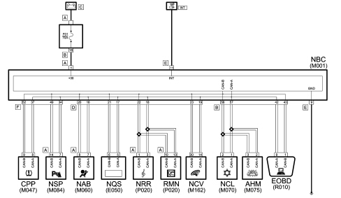
B-CAN
C-CAN
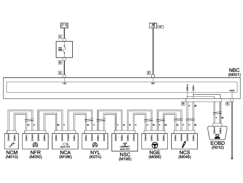
NBC Body Computer node
NGE Electric steering node
NYL Yaw sensor node
NFR Brake node
NCM Engine control node
NCS Suspension Control Node
NCA Twin clutch transmission
NSC Twin clutch transmission selection node
NQS Instrument panel node
NAB Airbag node
NSP Parking sensor node
NRR Radio receiver node
RNM Map radio navigator
NCV Bluetooth control unit node
NCL Climate control node
AHM Supplementary heater module
CCP Tyre pressure control Unit
EOBD Diagnosis connector

|
(the code used in wiring diagrams is shown in brackets) |
The structure of the communication lines includes:
-
A 50 kbit/s B-CAN type network. Specifications: presence of two network cables, B-CANb and B-CANa, resistant to network malfunctions; 29 bit standard
-
A 500 kbit/s C-CAN type network. Specifications: presence of two tangled network cables, C-CANH and C-CANL, not resistant to network malfunctions; 29 bit standard
Replacing and initializing network nodes
Some of the CAN nodes are programmed with default settings which the customer will discover on acquiring the vehicle.
The nodes storing this information are the:
- Body Computer;
- Instrument Panel Node;
- Bluetooth Control Unit Node;
- Radio Navigator Node;
- Climate Control Unit Node;
- Airbag Node

|
If the Body Computer is being replaced, an "identical copy" of the Body Computer must be obtained from the Spare Parts Dept. as a V.O.R. order supplying the vehicle chassis number: this copy will contain all the default settings entered into the new vehicle which are stored in the Parts Dept. database for the vehicle chassis number. |
|
|
If the other nodes described above are being replaced, the Spare Parts Dept. will send a blank component: once fitted, the initial default data must be transferred to it by carrying out the PROXI ALIGNMENT procedure using the Examiner. |
Battery disconnection
If the battery is disconnected,
- Body Computer;
- Instrument Panel Node;
- Bluetooth Control Unit Node;
- Radio Navigator Node;
- Climate Control Unit Node;
- Airbag Node
they keep the information received and do not need to be initialized after the battery is disconnected, whilst the other nodes lose some or all of the information memorized and should be initialized.
Logistic mode
Logistic mode: the software inside the Body Computer cut-out all vehicle electrical loads, except the main functions (vehicle starting, lights). This function makes it possible to save battery energy which is useful when the vehicle is parked, possibly for long periods, in forecourts before being sold.
|
|
The function should be disabled in the workshop before the vehicle is handed over to the customer. |
Deactivation procedure
The procedure is as follows:
- connect the diagnosis device terminal to the vehicle EOBD socket and turn the ignition ON.
- Check that the "alternator recharging" warning light is in flashing mode to indicate that the Logistic Mode low consumption mode is activated.
- Deactivate the low consumption supply mode by carrying out the fault diagnosis of the Body Computer using the Examiner.
- The Body Computer and all control units involved, on receiving the CAN message, will restore their full operation and send a confirmation message to the Body Computer node.
- Delete the error memory in all control units with a diagnosis function.
- Carry out a key OFF - key ON.
- Check that the "alternator recharging" warning light is on constantly.
Fault diagnosis and diagnosis connector
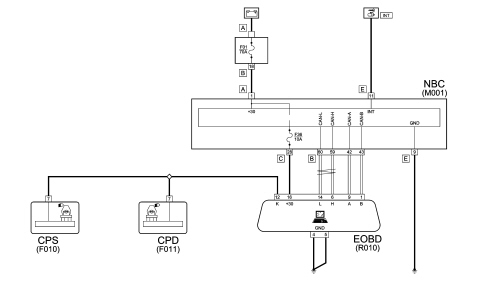
The diagnosis socket (EOBD) is external to the Body Computer node and joins the two CAN networks. Therefore, node diagnosis is not performed by means of diagnosis sent on communication networks, except for the two discharge gas headlight control units (CPS and CPD), which are connected to the diagnosis socket directly.
|
|
An A16HS diagnosis connector is needed in order to be able to converse with the various electronic units. |
Additional lines include the serial ISO 5 A-BUS line for alarm, wiper and lighting functions and a LIN serial line which connects the instrument panel to the rear seat belt fastened indicator display
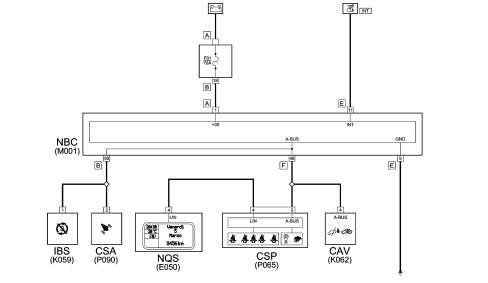
CSP rain/dusk sensor control unit
NQS Instrument panel node
CAV - Volumetric Alarm Control Unit
CSA Alarm siren control unit
IBS Intelligent Battery Sensor (only Start&Stop versions)
Body Computer node
Location of the Body Computer Node.
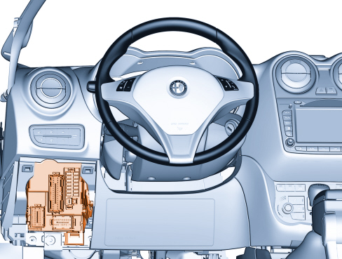
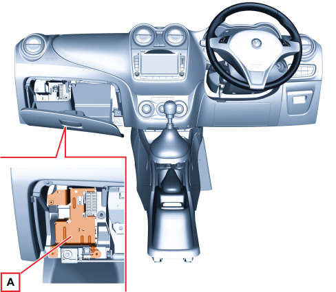
Right hand drive version:
The Body Computer Node is placed in the area under the dashboard, on the left, behind the glove compartment.
An anti-break plate A preserves it.
The rear part of the Body Computer Node is illustrated below.
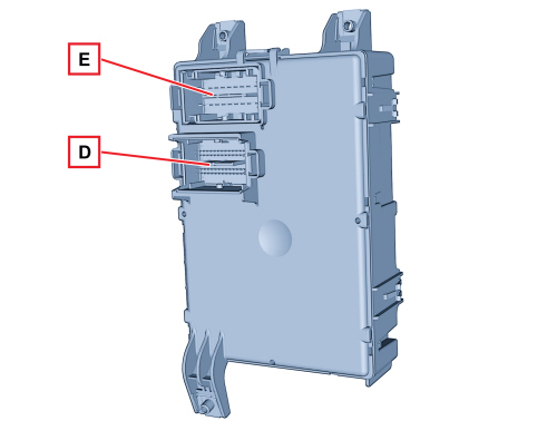

|
M001D connector pinout (dashboard wiring) |
|
|
Pin |
Function |
|
1 |
Immobilizer Aerial (Earth) |
|
2 |
Immobilizer Aerial (Signal) |
|
3 |
Negative signal from heated rear windscreen switch (NC) |
|
4 |
F serial line for ABS / LIN (NC) |
|
5 |
A-bus line for rain sensor (NC) |
|
6 |
Right direction indicators negative control from steering column stalk (NC) |
|
7 |
Hazard warning lights switch negative control |
|
8 |
"UP" negative control on driver's window (NC) |
|
9 |
VSO signal generation (NC) |
|
10 |
Hazard warning lights LED control (NC) |
|
11 |
Door status LED control |
|
12 |
Heated rear windscreen LED operation (NC) |
|
13 |
"DOWN" negative control on driver's window (NC) |
|
14 |
"UP" negative control on passenger's window (NC) |
|
15 |
"DOWN" negative control on passenger's window (NC) |
|
16 |
B CAN-A Airbag node |
|
17 |
B CAN-A NQS |
|
18 |
B CAN-A NRR / RNM |
|
19 |
B CAN-A Bluetooth |
|
20 |
B CAN-B Airbag node |
|
21 |
B CAN-B NQS |
|
22 |
B CAN-B NRR / RNM |
|
23 |
B CAN-B Bluetooth |
|
24 |
C CAN-H NCV (Stub) (NC) |
|
25 |
C CAN-H EOBD (Stub) (NC) |
|
26 |
C CAN-L NCV (Stub) (NC) |
|
27 |
C CAN-L EOBD (Stub) (NC) |
|
28 |
City button negative control (NC) |
|
29 |
Setup |
|
30 |
Front fog light switch signal (NC) |
|
31 |
A/C request signal (NC) |
|
32 |
Not connected |
|
33 |
Earth reference signal (NC) |
|
34 |
Reference earth to steering column switch unit signal |
|
35 |
Spring cable reference earth signal |
|
36 |
Main beam headlight/flasher negative control from steering column stalk |
|
37 |
LH control panel reference earth |
|
38 |
Light control negative control |
|
39 |
Door opening/closing switch signal |
|
40 |
Luggage compartment internal switch signal (NC) |
|
41 |
Cruise Control negative control |
|
42 |
Voltage stabiliser diagnosis |
|
43 |
S&S deactivation button |
|
44 |
Left direction indicators negative control from steering column stalk (NC) |
|
45 |
FN/RN control from control panel |
|
46 |
Not connected |
|
47 |
Not connected |
|
48 |
Not connected |
|
49 |
Control panel reference earth |
|
50 |
LH radio controls on the steering wheel (VOL-; VOL+; Mute; Voice) |
|
51 |
Side light control signal from steering column stalk |
|
52 |
RH radio controls on the steering wheel (SCAN -; SCAN +; Source; TEL) |
|
53 |
Not connected |
|
54 |
Windscreen wiper first speed negative control from steering column stalk |
|
55 |
Windscreen washer negative control from steering column stalk |
|
56 |
DNA selector control power |
|
57 |
Windscreen wiper intermittent speed negative control from steering column stalk (NC) |
|
58 |
Not connected |
|
59 |
Rear window wiper negative control from steering column stalk |
|
60 |
Radio lighting according to side lights |
|
M001E connector pinout (dashboard wiring) |
|
|
Pin |
Function |
|
1 |
INT/A from ignition switch |
|
2 |
Power (+30) (NC) |
|
3 |
Supply for airbag |
|
4 |
Power supply (+15) for radio (setup) |
|
5 |
Power supply (+15) for Bluetooth and voltage stabilizer (Start&Stop) |
|
6 |
INT/A (NC) |
|
7 |
Power (+15) for NQS |
|
8 |
Dipped headlight positive signal for headlight alignment control at NQS |
|
9 |
Power earth 1 for NBC |
|
10 |
Power earth 2 for NBC (NC) |
|
11 |
INT from ignition switch |
|
12 |
Power supply +30 for radio and voltage stabilizer (Start&Stop) |
|
13 |
Power supply (+15) for PND and AUX socket |
|
14 |
+30 NQS power supply |
|
15 |
Power (+15) for central control panel light |
|
16 |
Power (+15) for LH control panel light |
|
17 |
Power (+15) for steering wheel control lights |
|
18 |
Glove compartment light (SBMT.) |
|
19 |
+30 Bluetooth supply |
|
20 |
+30 radio amplifier enable |
The front part of the Body Computer Node is illustrated below.
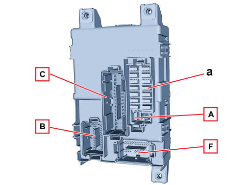
a: Fuses
M001A connector (front wiring): Body Computer power supply
|
M001B connector pinout (front wiring) |
|
|
Pin |
Function |
|
1 |
"N" command from DNA selector |
|
2 |
Start&Stop starting relay control |
|
3 |
WLM (+15) window winder |
|
4 |
Fog lights relay negative control |
|
5 |
Door open negative signal to NCA control unit (TCT) |
|
6 |
Heated rear window relay negative control |
|
7 |
Puddle light timer |
|
8 |
Right front direction indicator |
|
9 |
Right side direction indicator |
|
10 |
Left front direction indicator |
|
11 |
Left side direction indicator |
|
12 |
Lighting depending on side lights |
|
13 |
Right DRL light |
|
14 |
Comfort enable control for window winders and mirrors |
|
15 |
Right front side light (NC) |
|
16 |
INT/A relay control (NC) |
|
17 |
Door status LED control (NC) |
|
18 |
Hazard warning lights signal (NC) |
|
19 |
VSO signal for sunroof |
|
20 |
Hazard warning lights LED control (NC) |
|
21 |
Heated rear windscreen LED control |
|
22 |
Main beam headlight relay negative control |
|
23 |
Headlight washer relay negative control |
|
24 |
LH rear LED light feedback signal |
|
25 |
DNA selector earth |
|
26 |
Front and rear brake pad wear signal |
|
27 |
Brake light control from brake pedal (NO) |
|
28 |
Left DRL light |
|
29 |
Front left side light |
|
30 |
Front right side light |
|
31 |
"D" command from DNA selector |
|
32 |
"UP" switch signal on driver's window (NC) |
|
33 |
Negative signal from brake oil level sensor |
|
34 |
Brake light switch signal (N.C.) |
|
35 |
TPMS 1 signal (NC) |
|
36 |
TPMS 2 signal (NC) |
|
37 |
Outside temperature signal |
|
38 |
"UP" switch signal on passenger's window (NC) |
|
39 |
Windscreen wiper stop contact signal |
|
40 |
"DOWN" switch signal on driver's window (NC) |
|
41 |
Heated rear windscreen switch signal |
|
42 |
B-CAN A Diagnosis socket |
|
43 |
B-CAN B Diagnosis socket |
|
44 |
C CAN-H NBC (network start) |
|
45 |
C CAN-L NBC (network start) |
|
46 |
Cornering light control (NC) |
|
47 |
"DOWN" switch signal on passenger's window (NC) |
|
48 |
Open bonnet switch signal |
|
49 |
A/C request signal |
|
50 |
Tachometer sensor signal (NC) |
|
51 |
Door opening switch from driver's door |
|
52 |
Outside temperature sensor earth |
|
53 |
Open passenger door switch signal |
|
54 |
Open driver's door switch signal |
|
55 |
Serial line for ABS doors LIN (NC) |
|
56 |
A-BUS line |
|
57 |
B CAN-A Climate Control System Control Unit |
|
58 |
B CAN-B Climate Control System Control Unit |
|
59 |
C CAN-H |
|
60 |
C CAN-L |
|
M001C connector pin-out (front wiring) |
|
|
Pin |
Function |
|
1 |
Front left electric windows "DOWN" control (NC) |
|
2 |
Two-way pump (rear window washer) |
|
3 |
Windscreen wiper motor (low speed operation) |
|
4 |
INT power (NC) |
|
5 |
Power socket INT power supply |
|
6 |
INT seat heater control power |
|
7 |
INT to NO brake pedal power |
|
8 |
Engine compartment control unit relay switch INT power, reverse switch |
|
9 |
INT (NC) |
|
10 |
Power supply for left dipped headlight bulb |
|
11 |
LH headlight alignment corrector actuator |
|
12 |
+30 TPMS control unit, volumetric sensors, alarm siren |
|
13 |
Supply for rear window wiper |
|
14 |
Windscreen wiper motor (high speed operation) |
|
15 |
Two-way pump (windscreen washer) |
|
16 |
Central door locking (closing/opening) |
|
17 |
Front right electric windows "DOWN" control (NC) |
|
18 |
Front right window winder motor power |
|
19 |
Front left window winder motor power |
|
20 |
Puddle lights (SBMT) |
|
21 |
INT/A for engine compartment control unit |
|
22 |
INT for DNA selector lighting |
|
23 |
INT for gas discharge headlights |
|
24 |
INT for climate system assembly |
|
25 |
INT for brake and clutch pedal |
|
26 |
Right headlight alignment corrector actuator |
|
27 |
Power supply for right dipped headlight bulb |
|
28 |
+30 diagnosis socket |
|
29 |
+30 power for mirror control, climate control |
|
30 |
Tailgate unlocking control |
|
31 |
Joint door locking/unlocking |
|
32 |
Central door locking (DEAD-LOCK) |
|
M001F connector pin-out (rear wiring) |
|
|
Pin |
Function |
|
1 |
Rear left direction indicator |
|
2 |
Left side direction indicator (NC) |
|
3 |
Right rear direction indicator |
|
4 |
Fuel level sensor signal |
|
5 |
Right rear side light |
|
6 |
Left rear side light (NC) |
|
7 |
Negative signal from rear wiper cam |
|
8 |
Right brake light |
|
9 |
Front roof light timed control |
|
10 |
Left brake light |
|
11 |
Rear roof light control (NC) |
|
12 |
Puddle light control (NC) |
|
13 |
Front roof light power supply (SBMT) |
|
14 |
Parking sensor power supply |
|
15 |
Number plate lights |
|
16 |
LH stop light (N.C.) |
|
17 |
Fuel level negative signal (GND) |
|
18 |
Right side flasher (NC) |
|
19 |
Applied handbrake switch negative signal |
|
20 |
Left rear side light |
|
21 |
Not connected |
|
22 |
LH light diagnosis (NC) |
|
23 |
INT for TPMS control unit, suspension control |
|
24 |
INT for rain/dusk sensor, electrochromic mirror, sunroof control, Bluetooth controls, volumetric sensors |
|
25 |
Brake light control (NC) |
|
26 |
Luggage Compartment Light Power Supply (SBMT) |
|
27 |
Passenger sun visor light power supply (SBMT) |
|
28 |
Driver sun visor light power supply (SBMT) |
|
29 |
INT/A for luggage compartment control unit |
|
30 |
Lighting connected to position lights |
|
31 |
RF aerial (GND) coaxial cable |
|
32 |
INT/A relay control (NC) |
|
33 |
F serial line for ABS / doors LIN (NC) |
|
34 |
B CAN-A Parking sensor node |
|
35 |
Not connected |
|
36 |
Not connected |
|
37 |
B-CAN-A TPMS control unit |
|
38 |
Tailgate opening negative control from Soft Touch handle |
|
39 |
Open tailgate negative signal |
|
40 |
LH rear door negative signal (NC) |
|
41 |
FIS negative signal (NC) |
|
42 |
Not connected |
|
43 |
Not connected |
|
44 |
Right fog light control/reversing light control (NC) |
|
45 |
Right fog light control/reversing light control (NC) |
|
46 |
RF aerial signal (coaxial cable) |
|
47 |
WLM Comfort closing (NC) |
|
48 |
A-BUS line for rain/dusk sensor, volumetric sensors |
|
49 |
B CAN-B Parking sensor node |
|
50 |
Not connected |
|
51 |
Not connected |
|
52 |
B-CAN-B TPMS control unit |
|
53 |
After market anti-theft signal (NC) |
|
54 |
RH rear LED light feedback signal |
|
55 |
Not connected |
|
56 |
RH rear door negative signal (NC) |
|
57 |
Not connected |
|
58 |
Not connected |
|
59 |
Not connected |
|
60 |
Rear fog light |
The fuses in the Body Computer are illustrated in the diagram below.
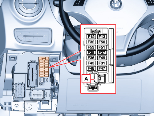
right hand drive version:
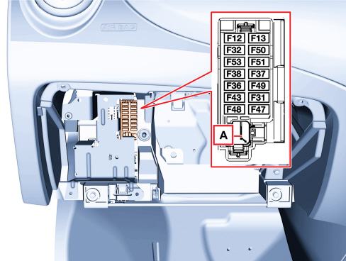
A. +30 NBC engine compartment control unit
FUSE IDENTIFICATION
|
Position |
Identification |
Type |
Users protected |
Capacity |
|
1 |
F12 |
A0 (mini) |
Right dipped headlight power supply |
7.5 A (15 A gas discharge) |
|
2 |
F32 |
A0 (mini) |
Roof lights and luggage compartment lights, sun visor lights, storage compartment light |
5 A |
|
3 |
F53 |
A0 (mini) |
NQS |
5 A |
|
4 |
F38 |
A0 (mini) |
Doors and luggage compartment central locking |
15 A |
|
5 |
F36 |
A0 (mini) |
EOBD diagnosis socket, radio, Bluetooth, radio navigator, alarm siren, volumetric sensors, car fan, TPMS, mirror controls, climate controls |
10 A |
|
6 |
F43 |
A0 (mini) |
Windscreen/rear window washer pump |
20 A |
|
7 |
F48 |
A0 (mini) |
Passenger side electric window |
20 A |
|
8 |
F13 |
A0 (mini) |
LH dipped headlight, headlight alignment corrector power supply |
7.5 A (15 A gas discharge) |
|
9 |
F50 |
A0 (mini) |
NAB (airbag) |
7.5 A |
|
10 |
F51 |
A0 (mini) |
Climate control, radio setup, Bluetooth, brake light switch (NC), clutch switch, reverse switch, engine compartment control unit relay, flow meter (JTD), water in filter sensor (JTD) |
5 A |
|
11 |
F37 |
A0 (mini) |
Brake light switch (NO), NQS, headlight corrector |
5 A |
|
12 |
F49 |
A0 (mini) |
Parking sensors, control lighting, electrochromic mirror, rain/dusk sensor, sun roof, PND socket, TPMS, cigar lighter lighting, seat belt display |
5 A |
|
13 |
F31 |
A0 (mini) |
INT/A for engine compartment junction unit relay |
5 A |
|
14 |
F47 |
A0 (mini) |
Driver side electric window |
20 A |
FUSE IDENTIFICATION (SINCE MODEL YEAR 2013)
|
Position |
Identification |
Type |
Users protected |
Capacity |
|
1 |
F12 |
A0 (mini) |
N.C. |
- |
|
2 |
F32 |
A0 (mini) |
N.C. |
- |
|
3 |
F53 |
A0 (mini) |
NQS |
5 A |
|
4 |
F38 |
A0 (mini) |
Doors and luggage compartment central locking |
15 A |
|
5 |
F36 |
A0 (mini) |
EOBD diagnosis socket, radio, Bluetooth, radio navigator, alarm siren, volumetric sensors, car fan, TPMS, mirror controls, climate controls |
15 A |
|
6 |
F43 |
A0 (mini) |
Windscreen/rear window washer pump |
20 A |
|
7 |
F48 |
A0 (mini) |
Passenger side electric window |
20 A |
|
8 |
F13 |
A0 (mini) |
Headlight alignment corrector |
5 A |
|
9 |
F50 |
A0 (mini) |
NAB (airbag) |
7.5 A |
|
10 |
F51 |
A0 (mini) |
Climate control, radio setup, Bluetooth, brake light switch (NC), clutch switch, reverse switch, engine compartment control unit relay, flow meter (JTD), water in filter sensor (JTD) |
5 A |
|
11 |
F37 |
A0 (mini) |
Brake light switch (NO), NQS, headlight corrector |
5 A |
|
12 |
F49 |
A0 (mini) |
Parking sensors, control lighting, electrochromic mirror, rain/dusk sensor, sun roof, PND socket, TPMS, cigar lighter lighting, seat belt display |
5 A |
|
13 |
F31 |
A0 (mini) |
INT/A for engine compartment junction unit relay |
5 A |
|
14 |
F47 |
A0 (mini) |
Driver side electric window |
20 A |
Engine compartment fuse box
The engine compartment junction unit is located on the left, protected by a special cover.
The cover removing-refitting sequence should be carried out correctly to avoid fitting the cover incorrectly which might allow fluid to enter the control unit
Op. 5505A28 CONTAINER FOR ADDITIONAL JUNCTION UNIT IN ENGINE COMPARTMENT - R.R.
|
|
It is not advisable to use water jets on the engine compartment junction unit guard during washing operations. |
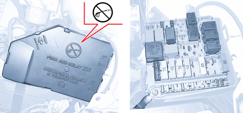
The engine compartment junction unit is incorporated in the engine compartment wiring harness and cannot be replaced on its own.
Fuses and relay switches
The location of the fuses in the engine compartment control unit is illustrated in the diagram below
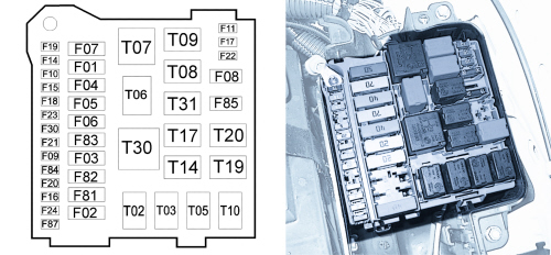
|
Fuse |
Capacity |
Users protected |
|
F01 |
70 A |
NBC (Body Computer) |
|
F02 |
40 A |
Luggage compartment control unit |
|
F03 |
20 A |
Ignition switch |
|
F04 |
40 A |
NFR 1 (pump) |
|
F05 |
70 A |
NGE |
|
F06 |
20/30/40 A |
Engine cooling electric fan low speed |
|
F07 |
30/40/50 A |
Engine cooling electric fan high speed |
|
F08 |
40 A |
Climate control fan (MY 2013) |
|
15 A |
Heated windscreen |
|
|
F09 |
5 A |
Heated blow-by |
|
20 A |
Headlight washer |
|
|
F10 |
15 A |
Horns |
|
F11 |
10 A |
NCM (secondary loads) |
|
F14 |
15 A |
Main beam headlights |
|
F15 |
10 A |
Suspension control unit |
|
7.5 A |
LPG sensors |
|
|
15 A |
NCA (TCT) |
|
|
30 A |
Heater PTC1 (JTD) |
|
|
F16 |
5 A |
+15 NCM, NCA (TCT) |
|
F17 |
7.5/10/15 A |
NCM |
|
F18 |
5 A |
NCM, NCA (TCT) |
|
F19 |
7.5 A |
Air conditioning compressor |
|
F20 |
30 A |
Rear windscreen demister and defroster |
|
F21 |
15 A |
Fuel pump |
|
F22 |
15/20 A |
NCM, main loads |
|
F23 |
20 A |
NFR 2 (valves) |
|
F24 |
5 A |
+15 NFR, NGE, yaw sensor |
|
F30 |
15 A |
Fog lights |
|
F81 |
20 A |
Hi-Fi amplifier and subwoofer (TCT transmission) |
|
60 A |
PTC2 heater (0.9 TwinAir) |
|
|
60 A |
Glow plug preheating control unit (JTD) |
|
|
F82 |
40 A |
TCT pump |
|
40 A |
PTC1 heater (0.9 TwinAir) |
|
|
50 A |
Heater PTC2 (JTD) |
|
|
F83 |
40 A |
Climate control system fan |
|
F84 |
15 A |
(TCT) transmission pump |
|
15 A |
LPG control unit |
|
|
20 A |
Hi-Fi amplifier and subwoofer (CM) |
|
|
F85 |
15 A |
Power sockets |
|
F87 |
7.5 A |
+15 mirror defroster and heated nozzles |
|
Relay |
Capacity |
Users operated |
|
T02 |
20 A |
Main beam headlights |
|
T03 |
20 A |
Horns |
|
T05 |
20 A |
Air conditioning compressor |
|
T06 |
30 A |
Engine cooling electric fan low speed |
|
T07 |
50 A |
Engine cooling electric fan high speed |
|
T08 |
30 A |
Climate control fan (MY 2013) |
|
20 A |
Heated windscreen |
|
|
T09 |
30 A |
Engine management system |
|
T10 |
30 A |
S&S starting inhibitor (with T20 locked) |
|
30 A |
LPG sensors |
|
|
20 A |
Headlight washer (version without S&S) |
|
|
T14 |
20 A |
Fog lights |
|
T17 |
20 A |
Fuel pump |
|
T19 |
30 A |
Heated rear window |
|
T20 |
30 A |
LPG control unit |
|
30 A |
TCT control unit |
|
|
30 A |
S&S starting |
|
|
T30 |
50 A |
Climate control system fan |
|
T31 |
20 A |
Power sockets |
Relay switches and fuses outside of the engine compartment junction unit
Some fuses and relay switches for some engine versions and trim levels are located in front of the engine compartment junction unit.
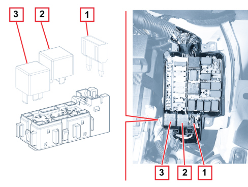
1 - Battery charge status sensor fuse (versions with Start&Stop)
1 - LPG control unit fuse (Euro 6 LPG version)
2 - Headlight washer relay switch (versions with Start&Stop)
2 - LPG power supply relay switch (Euro 4 LPG version)
3 - Heated blow-by relay switch (JTD versions, optional for cold countries)
ADDITIONAL FUSE BOX
A number of fuses are arranged in the luggage compartment on the rear left side panel.
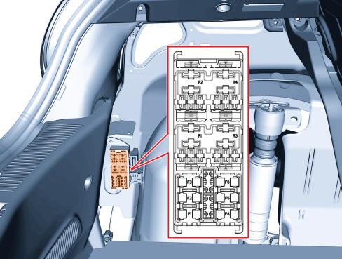
The following fuses are housed in the luggage compartment fuse box:
|
in the diagram |
in the wiring diagrams |
Users protected |
Capacity |
|
F1 |
F63 |
Sun roof |
20 A |
|
F2 |
F64 |
Not used |
- |
|
F3 |
F65 |
Rear power socket |
15 A |
|
F4 |
F60 |
HIFI amplifier (up to 08) |
15 A |
|
F5 |
F61 |
HIFI subwoofer (up to 08) |
10 A |
|
F6 |
F62 |
Heated seats |
15 A |
The following relay switches are housed in the luggage compartment control unit:
|
in the diagram |
in the wiring diagrams |
Users protected |
Capacity |
|
R1 |
T42 |
Rear power socket |
20 A |
|
R2 |
T43 |
Not used |
- |
|
R3 |
T40 |
Left heated seat |
20 A |
|
R4 |
T41 |
Right heated seat |
20 A |
The luggage compartment control unit is wired directly to the rear cable and does not have connections that can be disconnected; it can only be replaced by disconnecting the individual terminals; see
Op. 5505A14 SUPPLEMENTARY JUNCTION BOX IN LUGGAGE COMPARTMENT - R.R