INTRODUCTION
The climate control system fitted to the vehicle is used to alter the environmental properties of air taken into the passenger compartment (temperature and humidity), allowing the demisting of the glass surfaces and preventing the intake of pollutant substances, thereby making the environment in the passenger compartment more healthy.
The air conditioning system is a comfort factor that contributes to improving the physiological wellbeing of the vehicle occupants.
Climate control system components
The climate control system components are illustrated in the diagram below.
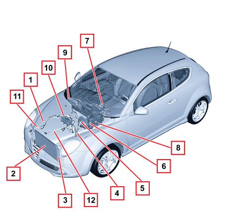
1 - Linear pressure switch
2 - Condenser
3 - Drier filter built into the condenser
4 - Low pressure pipe
5 - Expansion valve
6 - Evaporator
7 - Control panel
8 - Heater
9 - Duct/distributor unit
10 - Compressor
11 - High pressure gas pipe
12 - High pressure fluid pipe
Operating principle
The aim of refrigeration equipment is to absorb heat from an environment. In order to do this an air conditioner has recourse to certain fluids (known as refrigerants) capable of cooling down (lowering their temperature) and changing state (from liquid to gas) when they are subject to a large drop in pressure, thus expanding. They are therefore capable of absorbing heat from their environment. When the temperature increases, thereby also increasing the pressure, they change state again, from gas to liquid, and condense.
The first problem is therefore to liquefy this gas, which can be achieved simply by bringing it to a temperature below that of evaporation (or boiling) which, as has already been stated, is -26°C at atmospheric pressure for R134a.
In order for this to be achieved at ambient temperature which, in our case, may be rather high (in the engine compartment), it is necessary to increase the evaporation point of the gas so that it remains liquid until the moment it is made to expand, in order to produce the desired refrigerant effect.
To raise the boiling point of the gas its pressure must be increased, at the same time, decreasing the temperature.
In order for this to take place the system requires a certain amount of power. This power, supplied by the compressor, is subtracted from the power produced by the engine.
The operating principle of the refrigerant cycle phases in the air conditioning system for a motor vehicle can be summed up as follows.
The gaseous R134a refrigerant is drawn in by the compressor at a pressure of between 0.5 and 2 bar and is compressed at a value of between 10 and 17 bar. Boiling point becomes around 60 °C at these pressures.
This fluid is heated by the compression stage at 80 -100 °C, always in a gaseous state.It is heated in the compressor where, through the effect of the cooling air flow (produced by the vehicle moving forward or through the action of the fan) that passes through, it reaches condensation point, changing at high pressure to a liquid state.
Later on the refrigerant passes through a filter which has three functions: to trap the impurities, to absorb the dampness contained in the circuit and to work as a reserve reservoir for the actual refrigerant.
The refrigerant therefore reaches the expansion valve which introduces it into the evaporator where the pressure is around 1.5 atm. (1.52 bar). At this pressure the liquid/vapour system saturated with the refrigerant fluid is in equilibrium at a temperature of about -7 °C. At the same time, the air that passes through the evaporator (through the action of a fan), being at a considerably higher temperature than the refrigerant fluid it contains, causes it to boil and evaporate completely by imparting heat. When it cools down, the air deposits some of the humidity it contains on the evaporator fins in the form of droplets which are collected in a chamber and drained outside the vehicle.
The air, cooled and dehumidified in this way, is sent inside the vehicle. The refrigerant at the evaporator outlet is drawn in again by the compressor giving rise to a new cycle.
The route of the refrigerant fluid can be summarized as follows:
- In the compressor, the fluid from the evaporator is gaseous (temperature -5, -7°C, pressure 0.5 - 2 bar). Compression phase: the gaseous fluid is heated (temperature 80 - 100 °C, pressure 10 - 17 bar).
- Condenser - Compression phase: the fluid transmits heat to the outside, cools and returns to a liquid state (temperature 40 - 60°C, pressure 10 - 17 bar).
- Thermostatic expansion valve - Expansion phase - the fluid loses pressure (0.5 2 bar, possibly even 3 bar) becomes a gas + liquid mixture; the temperature is low, typical of air conditioning.
- Evaporator - Evaporation phase - the fluid becomes completely gaseous because the hot air driven by the fan is at a higher temperature than the refrigerant fluid and causes it to boil and evaporate completely, giving off heat. The temperature is low, typical of air conditioning (pressure 0.5 - 2 bar).
Types of system
This vehicle is available with different climate control systems for the passenger compartment:
- manual climate control
- dual zone automatic climate control.
Manual climate control: the user sets the air temperature, distribution and flow rate and they remain like that until they are altered by the user later on.
Automatic climate control (dual zone): the user can set the parameters and select automatic system management. If they so wish, the user can retain the facility to manage the system manually.
In addition, the automatic climate control system on this vehicle is the dual zone type (driver's zone and front passenger zone), in other words the system has dual controls for the driver and the passenger and is capable of managing the settings for the two users separately, varying the air temperature and distribution parameters (the flow rate cannot be different in the zones) with a certain degree of independence.
MANUAL CLIMATE CONTROL SYSTEM
The manual climate control system control panel is illustrated in the diagram below.
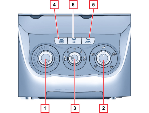
1 - Air temperature adjustment knob (hot/cold air mixing)
2 - Passenger compartment air distribution selection knob
3 - Fan speed selection knob
4 - Heated rear windscreen and exterior rear view mirror defrosting on/off button
5 - Interior air recirculation on/off button
6 - Climate control compressor on/off button
Operation
The maual air conditioner allows the use to manage the temperature and intake of air into the passenger compartment using the knobs and control buttons.
The following parameters/functions can be altered manually:
- Temperature
- Distribution in 5 positions
- Fan speed
- Engagement of compressor
- Recirculation.
The transmission of the air mixing and air distribution commands from the knobs to the climate control casing takes place by means of bowden cables.
The recirculation is implemented by means of an electric motor.
The compressor can only be activated if a fan speed is set.
AUTOMATIC CLIMATE CONTROL
The automatic climate control is managed by a control unit which is capable, thanks to an extremely sophisticated operating logic, of controlling the temperature within the two passenger compartment zones, either heating or cooling the air to produced the desired comfort level.
The climate control system automatically regulates the following parameters/ functions:
- Air temperature at the driver's/passenger side vents
- Fan speed
- Driver/passenger side air distribution
- Engagement of compressor
- Recirculation.
Controls
All the non adjustment buttons are dual (ON/OFF) including the recirculation.
The control panel for the climate control system control unit is illustrated in the diagram below.
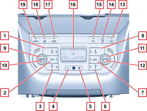
1 - Left DEF air distribution button
2 - Left VENT air distribution button
3 - Left FLOOR air distribution button
4 - Fan speed decrease button
5 - Fan speed increase button
6 - Right DEF air distribution button
7 - Right VENT air distribution button
8 - Right FLOOR air distribution button
9 - Driver's temperature adjustment knob
10 - Left AUTO mode button
11 - Passenger side temperature adjustment knob
12 - Right AUTO mode button
13 - Heated rear windscreen on button
14 - Defrost button
15 - Control unit off button
16 - Display
17- Recirculation button
18 - Compressor on button
19 - Passenger mode adjustment button
Climate control system control unit
The climate control system is managed automatically by an electronic control unit known as the Climate Control Node (NCL) which maintains the air climate control conditions set and, therefore, desired by the user (or users).
The NCL is connected to the vehicle's electrical system B-CAN.
The NCL is incorporated in the climate control system control panel fitted in the dashboard in the middle. The diagram illustrates the back of the control unit showing the connections to the electrical system and the connector pin out.
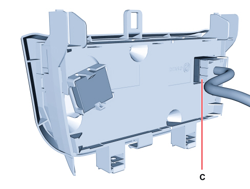
C control unit connector
Control unit pin out
|
PIN |
FUNCTION |
|
01 |
CAN L line |
|
02 |
CAN H line |
|
03 |
Not connected |
|
04 |
Not connected |
|
05 |
Fan control |
|
06 |
Not connected |
|
07 |
Solar sensor power supply |
|
08 |
Not connected |
|
09 |
Right VENT treated air temperature sensor |
|
10 |
Left solar sensor analogue input |
|
11 |
Analogical earth |
|
12 |
Recirculation open control |
|
13 |
Not connected |
|
14 |
Not connected |
|
15 |
Not connected |
|
16 |
Not connected |
|
17 |
Left FLOOR treated air temperature sensor |
|
18 |
Left VENT treated air temperature sensor |
|
19 |
Right solar sensor analogue input |
|
20 |
Right FLOOR treated air temperature sensor |
|
21 |
Not connected |
|
22 |
Recirculation closed control |
|
23 |
Not connected |
|
24 |
Shared right mixture actuator |
|
25 |
Left mixture actuator feedback |
|
26 |
Right mixture actuator feedback |
|
27 |
Right distribution actuator feedback |
|
28 |
Left distribution actuator feedback |
|
29 |
Fan feedback |
|
30 |
Power supply from battery |
|
31 |
5V external power supply |
|
32 |
Left mixture actuator control |
|
33 |
Shared right distribution actuator |
|
34 |
Right distribution actuator control |
|
35 |
Right mixture actuator control |
|
36 |
Left distribution actuator control |
|
37 |
Left mixing actuator common |
|
38 |
Shared left distribution actuator |
|
39 |
Ignition-operated power supply |
|
40 |
Electronic earth |
Operating logic
The control unit that manages the automatic climate control is capable of producing and maintaining the desired comfort within the two areas of the passenger compartment by controlling the following parameters and functions:
- Air temperature at the driver's/passenger side vents;
- Fan speed (continuous variation);
- Air distribution;
- Engagement of compressor;
- Recirculation.
The climate control system control system is managed in such a way as to regulate the "equivalent temperature", i.e. the temperature correlated to the thermal sensation and defined by a series of parameters such as humidity, passenger compartment air flow rate, average temperature, etc.
Therefore the user sets an equivalent temperature and the system acts on all the variables in its control to ensure the thermal sensation requested; for this reason the temperature in degrees centigrate measured in the passenger compartment may not coincide with the temperature shown on the display.
The following parameters/functions can be altered manually:
- Driver's/passenger side temperatures
- Fan speed
- Distribution in 7 positions (driver / passenger).
- Compressor
- Defrosting/demisting function
- Recirculation.
Manual selections always take priority over automatic ones and are memorized until the user switches back to automatic operation.
The manual setting of a function does not adversely affect the control of the other automatic functions, in particular the temperature control is always automatic when the system is operating.
Each time it is switched on, the system restores the conditions memorized when it was turned off, except for:
- the MAX DEF function which is reset;
- the recirculation which, with the compressor OFF, is forced open;
- fan speed (continuous variation).
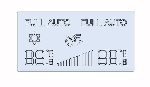
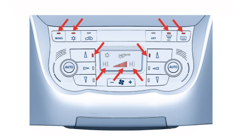
The display of the control unit is illustrated below.
Temperature setting knob
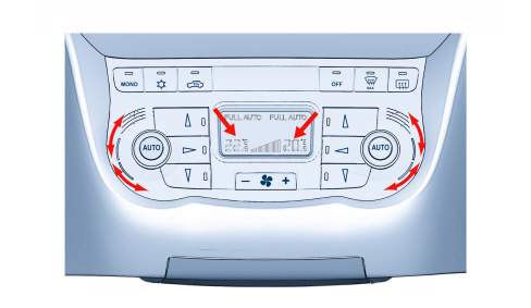
By turning the knob to the desired zone (driver's knob 9 or passenger knob 11) the temperature is increased (clockwise) or decreased (anti-clockwise).
The temperature settings are memorized at the key off and then restored at the next key on.
The knob works in steps of 0.5 °C and one complete revolution of the knob produces 34 steps.
The temperature range that can be set is from 16 °C to 32 °C. Below 16 °C the setting is LOW, whilst above 32 °C it is HI. In addition, the permitted difference in temperature settings between the left and right sides is 7°C.
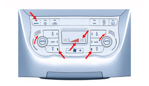
High condition (hi)
The HI condition or maximum heating (shown on the display in the field E1 and E2) is reached by setting an equivalent T requested by the user above 32 °C.
The request by the user (driver's knob 9 or passenger's 11) for the HI condition or maximum heating switches off the FULL AUTO symbol (A in the display) and forces the MONO condition (B in the display) regulating the following parameters:
- The status of the recirculation and the compressor remains unaltered;
- The mixer flaps are in the maximum heating position;
- The distribution flap is in the FLOOR position and the LED is on (in button 3);
- The air flow rate is at the maximum value of 10 bars equal to 90%.
All the manual settings are allowed in the HI condition in accordance with the planned logics.
The Auto command is accepted, the HI function and the 32 °C temperature setting for both zones are reset.
If the driver turns the temperature setting (knob 12) this moves the passenger setting out of HI, to 32 °C.
If the passenger turns the temperature setting (knob 13) this also moves the driver's setting out of HI (to 32 ºC), then changing their own settings placing the system in the Dual Zone mode.
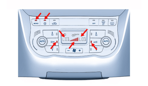
Low condition (lo)
The setting of the LO condition or maximum cooling (shown on the display in the field E1 and E2) switches off the FULL AUTO symbol, forces the MONO condition and involves the following actions:
- Enablement of the compressor (I shown in the display);
- Mixer flaps in maximum cold position;
- Distribution flap in VENT position and LED on;
- The air flow rate is at the maximum value of 10 bars equal to 90%.
- Recirculation remains unchanged as requested by user.
All the manual settings are allowed in the LO condition in accordance with the planned logics.
The Auto command is accepted, the LO function and the 16 °C temperature setting for both zones are reset.
If the driver turns the temperature setting this moves the passenger setting out of LO to 16° C
If the passenger turns the temperature setting this also moves the driver's setting out of LO (to 16 ºC), then changing their own setting placing the system in the Dual Zone mode.
The flashing logic is valid, if the compressor is disabled after the LO request and the recirculation is in the forced open position.
Auto mode button
Pressing this button (10) makes the FULL AUTO logo appear and the system is run by the automatic management which controls:
- Distribution of the air (on the side involved);
- Fan speed;
- Compressor;
- Recirculation.
If the FULL AUTO logo and the compressor enablement button LED are lit up this means that all the above functions are controlled automatically
The word FULL goes out when at least one manual distribution, flow rate, recirculation or compressor command is carried out. At this point the system only returns to FULL AUTO mode if the AUTO button is pressed again.
If the compressor is switched off (LED and snowflake symbol off), the system may no longer be capable of controlling/maintaining one or both of the temperatures set. In these conditions the "snowflake" symbol flashes in the climate control display.
If, at the end of the flashing, the compressor has not been enabled, then the FULL logo (or the AUTO logo only if the FULL logo was already off) will go out .
If the compressor disabling button is pressed, the AUTO logo does not necessarily go out.
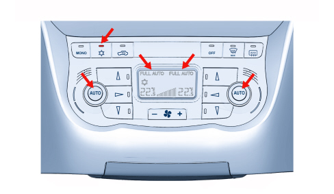
Air distribution buttons
There are 7 positions for the air distribution and the system manages the distribution automatically displaying its selection by the LEDs in the control buttons lighting up.
One of the 7 possible positions can be selected manually (by operating buttons 1, 2, 3, 6, 7, 8) using the combination logic described below.
MAIN DISTRIBUTIONS:
- DEF (hot/cold or mixed air for defrosting) (button 1, 8)
- VENT (hot/cold or mixed ventilated air at the front) (button 2, 7)
- FLOOR (hot/cold or mixed air at the floor) (button 3, 6)
COMBINED DISTRIBUTIONS THAT CAN BE IMPLEMENTED:
- BILEVEL (VENT-FLOOR) (2-3, 7-6)
- HEAT (DEF-FLOOR) (1-3, 6-8)
- HI LEVEL (DEF-VENT) (1-2, 7-8)
- TRI LEVEL (DEF-VENT-FLOOR) (1-2-3, 6-7-8)
DISTRIBUTION NOT ALLOWED:
- all OFF.
With the main distribution active (one LED on), the following takes place when the same button is pressed:
- the distribution remains unchanged;
- the system moves to manual (the FULL logo goes out if it is on).
The left (driver's) DEF distribution is dominant compared with the passenger side and therefore each time the driver sets the distribution to DEF it also forces the passenger distribution to DEF. The passenger can get out of this situation by operating any of the right distribution controls. Later on, when the driver selects another position outside of DEF, the passenger position remains DEF (if the MONO button is off). The passenger can change this setting by operating any of the distribution buttons.
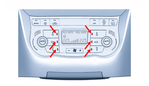
Automatic distribution
In automatic mode the control of the distribution is managed by an algorithm that governs the shifts for the various functions based on certain conditions.
Depending on the driver TTP, there are 3 possible situations at the key on:
- driver TTP <= 20°C: VENT distribution;
- driver TTP > 20°C, <29°C: BILEVEL distribution;
- driver TTP >= 29°C: FLOOR distribution.
The system also governs the shift between the different distributions depending on the outside conditions and system requests. Starting from BILEVEL distribution the following cases occur.
Shift from FLOOR distribution if the following are present simultaneously:
- Outside temperature < 11°C
- Solar rays < 250 W/m2
or if:
- TTP > 29 >C°C
Return to BI-LEVEL distribution if the following are present simultaneously:
- Outside temp > 15 °C Outside temperature > 13 °C or Solar rays > 400 W/m2
- TTP < 25°C
Shift to VENT distribution if the following conditions are present simultaneously:
- Outside temperature > 19 °C or solar rays > 600 W/m2
- TTP < 16 °C
Return to BI-LEVEL distribution if the following are present simultaneously:
- Outside temperature < 17 °C
- Solar rays < 450 W/m2
Or if:
- TTP > 20 °C
In addition to controlling the distribution the system displays its selection by lighting up the LEDs in the control buttons.

|
The TTP temperature is the planned treated air temperature (calculated using the software algorithm). |
Recirculation
The recirculation button and LED operate with a rolling logic (if the climate control system control unit is switched on); if the button is pressed repeatedly two possible types of operation described below are called up:
- Recirculation forced closed (passenger compartment air)
- Forced recirculation on (external air)
RECIRCULATION FORCED CLOSED
This type of operation is signalled by the AUTO symbol in the display being switched off, the recirculation LED (in button 17) on and the "recirculation" logo on. The closing of the recirculation flap is controlled.
The timed reopening every 25 minutes is valid continuously with the recirculation closed.
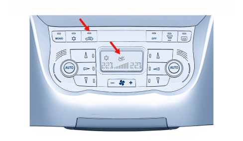
RECIRCULATION FORCED OPEN
This type of operation is signalled by the AUTO symbol in the display being switched off, the recirculation LED (in button 17) on and the "outside air" logo on. The forced opening of the recirculation flap is controlled.
The management of the recirculation button with the climate control system OFF is included in the paragraph describing the OFF button.
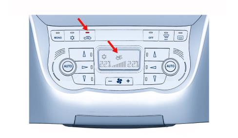
Air flow rate variation control (fan)
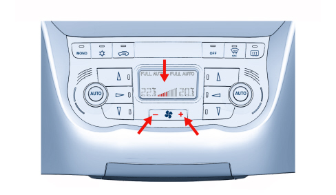
The air flow rate can be adjusted manually (using buttons 4 and 5) to 12 settings (plus switching off) displayed by a bar graph (G in the display) with 12 steps.
To increase the air flow rate in the passenger compartment, use the button with the "+" symbol (5 in the panel) and to decrease it use the "-" button (4 in the panel).
In automatic mode the speed is controlled continuously by the control unit and shown on the display by a number of bars proportional to the flow rate lighting up.
If the ventilation control is operated manually, the FULL AUTO condition is exited.
At the key on, if the automatic mode is on, the air flow rate is at the first bar (minimum flow rate) until the engine is started.
If the compressor is disabled it is possible to operate the ventilation manually until no bars are shown on the display representing the minimum flow rate.
Whilst with the compressor enabled and the engine started the manual ventilation cannot go below the value for the flow rate corresponding to one bar, to prevent the compressor from freezing.
Compressor enablement
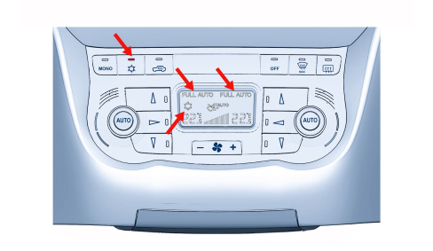
The LED in the compressor button (18) indicates the setting desired by the user: if the LED is on, the user wishes the compressor to be activated.
The snowflake symbol in the display indicates the enablement of the compressor: if it is on the compressor is enabled, i.e. there is an activation request.
With the LED on, pressing the button (18) switches off the LED and disables the compressor. This selection remains memorized indefinitely even after the vehicle has been switched off, the same as for the other manual controls.
The button has a dual function and therefore pressing it a second time re-enables the compressor and switches on the LED.
Management of the compressor
Pressing the compressor button (18) enables the compressor and switches on the LED.
From this moment, if there are requirements relating to the outside temperature, the system produces the necessary cold for controlling the climate control system inside the passenger compartment with the dehumidification effect of the evaporator.
This functional state is maintained even after the next key off/on.
There are some limits set by the outside temperature which restrict the operation of the compressor:
- if the outside temperature < 3°C the compressor is disabled (the snowflake symbol in the display is off);
- if the outside temperature > 5°C the compressor is enabled (the snowflake symbol in the display is on).
|
|
Enabled means the activation request to the engine management. |
FLASHING OF THE SNOWFLAKE SYMBOL
When the user disables the compressor the following takes place.
The LED in the compressor button (18) and the snowflake symbol in the display go out.
The word FULL in the display switches off.
The check verifies whether, with the current outside temperature, the system is capable of reaching/maintaining the requested temperature:
- If the answer is YES, then the system works normally and is capable of meeting the requirements even without the compressor switched on.
- If the answer is NO, then the system is not capable of meeting the user's requirements and signals this by making the temperature setting figures and the snowflake symbol in the display flash.
At the end of the signalling, if the compressor button is not pressed, the AUTO logo in the display goes out and the flashing cycle is reactivated at the next key on.
The flashing will not take place if the outside temperature is <= 3°C.
The system will switch on the snowflake symbol as soon as the outside temperature is >= 5°C.
Switching off control unit (off)
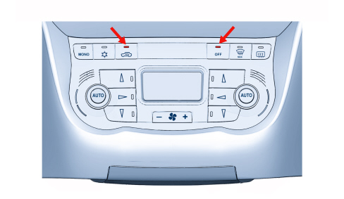
Pressing the OFF button (15) results in:
- memorizing of the current status;
- switching on of the LED in the OFF button;
- fan excluded;
- compressor excluded;
- mixer in max cold position;
- distribution in DEF/VENT.
In the OFF state the heated rear windscreen button (13) is managed normally without activating the climate control system.
In the OFF position the recirculation button has a dual function (ON/OFF) opening (LED off) and closing (LED on) the flap.
Pressing any button afterwards (except the recirculation and heated rear windscreen) switches the system back on, activates the function requested, if it was not (otherwise it confirms it) and restores all the other operating conditions memorized previously. Pressing the OFF button a second time also restores all the conditions prior to switching off, except the recirculation.
If the system is turned back on again through a distribution command, the main distribution requested is implemented.
Mono control
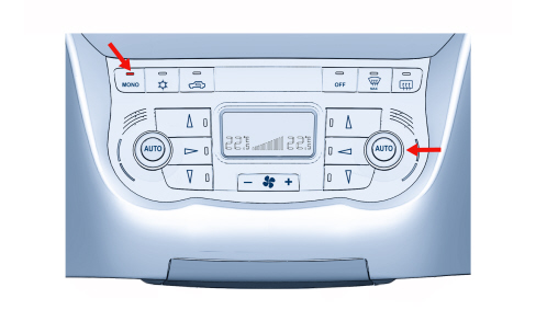
Pressing the MONO button (19 in the panel) determines the following actions:
- the temperature set on the passenger side is made the same as that set by the driver.
- the management of the air distribution set on the passenger side is made the same as that set on the driver's side; in manual mode the passenger distribution will be the same as that set by the driver, in automatic mode the passenger and driver distribution will be controlled by the automatic function.
- the MONO button LED comes on.
|
|
From that moment the system behaves like a SINGLE ZONE system. |
The return to DUAL ZONE (with the consequent switching off of the word MONO) is managed by the system by pressing the mono button again or altering the temperature and/or distribution on the passenger side.
These functional states are maintained even after subsequent KEYS OFF/ON.
Maximum defrosting button
The MAX DEF procedure manages the air distribution and flow rate with the aim of demisting the windows as quickly as possible (also managed with the engine switched off, but with the minimum flow rate).
The activation of the function lasts for 3 minutes, starting from when the temperature of the coolant exceeds a pre-set value.
When the MAX DEF button (14 in the panel) is pressed, the system carries out the following operations:
- Switching on of the MAX DEF LED (in button 14);
- Memorizing of the functional status and previous displays of MAX DEF control;
- Switching off of the LEDs/logos relating to the FULL AUTO, RECIRCULATION functions;
- Switching on of the DEF distribution, compressor enablement, MONO, recirculation open and heated rear windscreen LEDs;
- Display of the max hot temperature (HI) on both the side figures;
- Display of the ventilation in the display.
The following controls are also activated:
- Air flow rate 80% of the max flow rate;
- Distribution flap in DEF position;
- Mixture flaps in MAX HOT position;
- Air intake flap forced open (dynamic);
- Compressor function enabled;
- Rear windscreen defrost function.
The air flow rate can be varied (up/down), during the operation of the MAX-DEF, at will and the heated rear windscreen deactivated.
It is not possible to:
- Alter the temperature setting (driver/passenger).
- Alter the distribution setting.
- Alter the recirculation setting.
It is possible to interrupt the MAX-DEF function by activating any one of the climate control buttons (recirculation, compressor enablement, Auto, Mono, MAX-DEF, OFF, temperature and distribution) implementing the return to the prior to the MAX DEF plus the implementation of the control for the button pressed.
The management of the MAX-DEF procedure takes priority over the management of the following procedures:
- LO (max cold).
- HI (max hot).
If in progress, the execution is interrupted if the MAX DEF procedure is activated.
Heated rear window
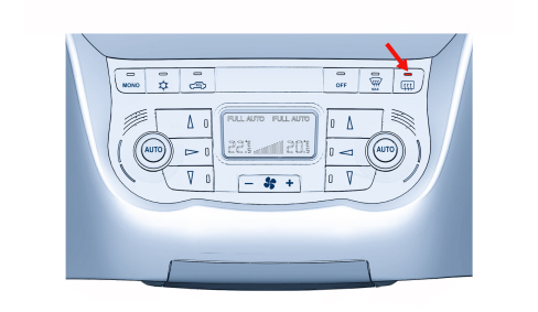
The rear defrosting is implemented both with the appropriate button pressed and through the Max-Def procedure.
The operating status is displayed by the relevant led switching on or off. The function requesting the activation of the heated rear windscreen is only subject to the presence of the key-on.
The HEATED REAR WINDSCREEN function is not memorized at the key-off.
Switching on after the vehicle has stopped
On switching on the various parameters are controlled manually or automatically depending on the selections made by the user before switching off.
Therefore all the manual interventions made before switching off the vehicle are memorized and maintained the next time the vehicle is started up.
|
|
If at the previous key off, the control was in MAX-DEF, at the next key on the system will assume the position memorized before MAX-DEF. |
Self-learning procedure
After the control unit or one of the actuators (excluding the recirculation one) has been replaced, it is necessary to proceed as follows.
CONTROL UNIT REPLACEMENT
Some of the CAN nodes, including the climate control system control unit, are programmed with default settings that the customer will find when they purchase the vehicle. If the control unit is being replaced, the Parts Dept. will send a blank component: once fitted, the data memorized by the Body Computer must be transferred to it by carrying out the PROXI ALIGNMENT procedure using the Examiner.
ACTUATOR REPLACEMENT
The self-learning procedure must be carried out using the Examiner (automatic procedure) or following the instructions given below (manual procedure).
1. Carry out the key on and within 40 seconds press the AUTO and MONO buttons simultaneously and keep them pressed.
2. After a few seconds a figure will appear in the left temperature display and decrease (from 05 to 00) (count down) indicating the remaining time before the start of the procedure (keep the AUTO and MONO BUTTONS PRESSED).
3. When the left temperature reaches the value (00), releasing the auto and mono buttons will initiate the procedure lasting about 40 seconds.
4. Entering into local fault diagnosis, at the end of the procedure, the right temperature may display the following values:
|
00 |
SELF-LEARNING taken place with OK outcome |
|
01 and flashing |
SELF-LEARNING taken place with not OK outcome |
|
02 |
SELF-LEARNING in progress |
|
03 and flashing |
SELF-LEARNING not completed |
The self-learning procedure does not take place if the AUTO and MONO buttons are released before the left temperature reaches zero.
The control unit makes the left temperature flash if the self-learning has not been carried out or if the result is not positive.
FORCED EXIT FROM THE PROCEDURE
When in progress, the self-learning procedure may be:
1. Aborted: when the user deactivates the key on signal.
In this case the system exits the procedure in a controlled manner without changing the state of the self-learning information memorized previously in the EEPROM and memorizes the data relating to the "self-learning not carried out" state.
2. Interrupted: when the +Battery starts to fail
If this takes place whilst the data is being stored in the EEPROM, the system does not manage to guarantee this information and the data relating to the "self-learning not carried out" state is memorized.
PROBLEMS DURING THE SELF-LEARNING PROCEDURE
If the procedure cannot be completed properly due to a problem with one or more of the actuators, the system exits the procedure without modifying the data memorized previously in the EEPROM and memorizes the information relating to the "self-learning not carried out" state.
COMPONENTS
Air conditioning unit
The unit comprises two modules which contain:
- the fan
- the evaporator
- the heater radiator
- the pollen filter
- the lower/upper mixed air temperature sensors (for the automatic version)
- the flap control actuators.
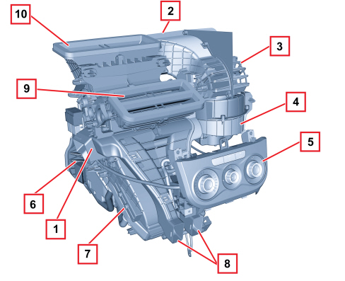
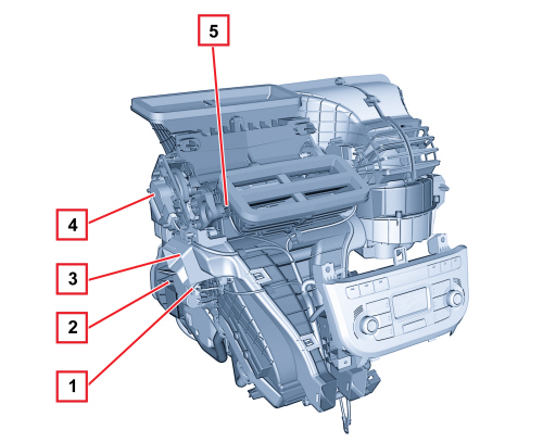
1 - Duct/distributor assembly
2 - Outside air intake
3 - Recirculation air intake
4 - Electric fan
5 - Control panel
6 - Evaporator
7 - Heater
8 - FLOOR air outlet
9 - VENT air outlet
10 - DEF air outlet
Automatic climate control system control unit
The diagram below shows the automatic climate control system components.
The structure of the unit is similar to the manual one and features electric motors, for moving the various flaps, controlled by the climate control system control unit:
- recirculation actuator,
- right side mixture actuator,
- left side mixture actuator,
- right side distribution actuator,
- left side distribution actuator.
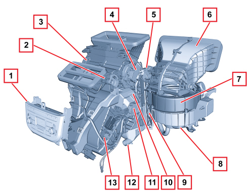
1 - Climate control system controls
2 - Right upper mixed air temperature sensor
3 - Climate control unit box
4 - Right air distribution actuator
5 - Air intake actuator (recirculation)
6 - Air vent box
7 - Fan
8 - Fan motor
9 - Pollen filter
10 - Right lower mixed air temperature sensor
11 - Right air mixer actuator
12 - Condensation drainage pipe
13 - Additional heater (PTC)
1 - Left air mixer actuator
2 - Evaporator
3 - Left lower mixed air temperature sensor
4 - Left air distribution actuator
5 - Left upper mixed air temperature sensor
Temperature sensors
There are four temperature sensors on the duct / distributor that provide the climate control system control unit with a signal relating to the temperature of the air coming out of the vents on both the left and right sides. Two sensors are located by the FLOOR vents and the other two are inside the centre dashboard vents.
The system also includes the passenger compartment air sensor (housed in the climate control system control unit) and the outside temperature sensor (located in the lower part of the right exterior rear view mirror).
Automatic system operation
The air is drawn in by the fan through the outside air intake or through the internal air intake. It passes through the pollen filter and reaches the main body. From there it passes through the evaporator and reaches the mixing and distribution area. The temperature of the air to be sent to the vents is determined by the position of the mixture flaps which have the task of shuttering the flow of air coming from the outside directly to the distribution area or the heat exchanger. An internal partition separates the left and right areas of the main assembly.
Solar sensor
The solar sensor is located in the top part of the dashboard at the base of the windscreen and its function is to transform the light signals (lux or kcal/m2) into a proportional linear electrical signal. The sensor is a particular type of diode (photodiode) which can vary its conduction depending on the quantity of light it comes into contact with; in practice, the incident light which comes into contact with the photodiode small lens releases electrons from the crystalline structure.
As a result electrons and free gaps appear in excessive numbers.
They are directed towards the spatial or photodiode junction zone (NP) and increase the photoelectric current in proportion to the intensity of the light. In order to achieve a very high response speed, the photodiode is equipped with a small lens which has the task of improving the focus of the light on the semiconductor junction (NP) which makes up the photodiode.
The control unit (NCL), using this signal, alters the temperature parameters decreasing it and at the same time acting on the distribution of the air.
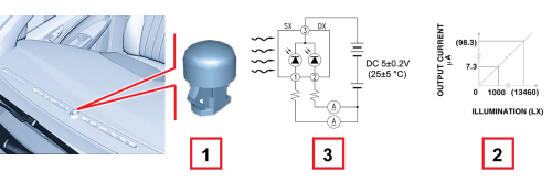
1 - Solar sensor
2 - Output current lighting typical diagram
3 - Diagram showing operation of solar sensor
Manual climate control unit
The unit is similar to the automatic one and features the following differences:
- no partition between the two zones,
- no temperature sensors,
- individual mixture and distribution flaps controlled by bowden cables,
- resistive type fan speed governor,
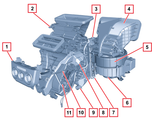
1 - Climate control system controls
2 - Climate control unit box
3 - Air intake actuator (recirculation)
4 - Air vent box
5 - Fan
6 - Fan motor
7 - Pollen filter
8 - Air mixing flap control mechanism
9 - Condensation drainage pipe
10 - Air mixing bowden cable
11 - Additional heater (PTC)
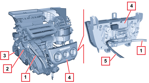
1 - Air distribution bowden cable
2 - Air distribution flap control mechanism
3 - Evaporator
4 - Climate control system controls
5 - Air mixing bowden cable
Expansion valve
The section of the expansion valve and the main parts are illustrated in the diagram below.
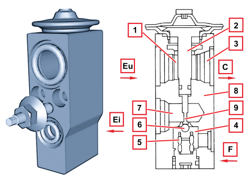
1 - Fluid outlet duct from the evaporator
2 - Heat sensitive element
3 - To the compressor intake connector
4 - Pressurized fluid
5 - Counter spring
6 - Ball and calibrated port
7 - Expanded fluid (at the evaporator inlet connector)
8 - Valve body
9 - Rod
C - To the compressor
F - To the drier filter
Ei - Evaporator inlet
Eu - Evaporator outlet
The tasks of this valve are to:
- Separate the high pressure circuit from the low pressure circuit;
- Expand the refrigerant (change in state from liquid to gas);
- Regulate the evaporation process (flow rate);
- Regulate the evaporation temperature;
- Protect the compressor from refrigerant fluid.
The thermostatic expansion valve, fitted on the evaporator inlet/outlet ducts, has the task of regulating the flow and expansion (drop in pressure) of the R134a refrigerant before entering the evaporator.
The automatic regulation of the size of the passage for the gas inside the expansion valve is produced by a sensitive bulb which measures the temperature of the refrigerant fluid and depending on this suitably adjusts the size of the opening that the gas passes through by means of a special spring that moves a shutter determining the extent of the expansion.
The increase in temperature at the evaporator outlet, detected by the sensitive bulb, opens the valve with a consequent increase in the flow rate of the refrigerant in the evaporator.
Conversely, low temperatures involve a reduction in the size of the gas port, determining a decrease in the flow of gas.

|
The valve regulation screw is calibrated during production and should NOT be tampered with, in order to avoid adversely affecting the efficiency of the air conditioning system. |
The expansion valve (A) is directly accessible from the engine compartment; see the diagram below:
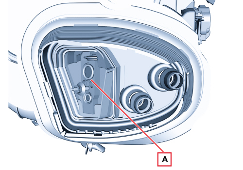
A - Expansion valve
This type of expansion valve has two different refrigerant fluid flows:
- Lower flow, from point (4), gas coming from the drier filter, to point (7), gas outlet towards the evaporator, containing the overheating spring (5) and the modulating element which, in this case, is the ball (6) housed in the calibrated duct.
- Upper flow, from pint (1), gas coming from the evaporator, to pin (3), gas outlet towards the compressor, containing the thermostatic sensor (2) which is connected to the upper part of the diaphragm and to the ball (6).
The flow rate control function is exerted through the movement of the ball (6) connected, via the rod (9), to the thermostat sensor (2).
The action of the ball (6) is opposed by the spring (5) which is suitably calibrated and ensures that the refrigerant in the evaporator is in a gaseous state without the presence of any fluid which, if drawn in by the compressor, could damage it.
The position of the ball (6) depends on the difference in pressure acting on the diaphragm inside the sensor (2); this, in turn, depends on the temperature of the refrigerant leaving the evaporator (upper flow of the valve).
High evaporator (1) gas outlet temperatures, corresponding to conditions where heat dissipation is high, increase the pressure inside the thermostatic sensor (2); this involves the movement of the rod (9) and the ball (6) connected to it, which increases the area of the flow and, as a result, the refrigerant (7) flow rate.
The opposite takes place when the temperature of the gas coming out of the evaporator (1) is low.
Linear pressure switch
The linear pressure switch controls the correct operation of the system, replacing the task performed by the quadrinary pressure switch. By continuously analysing the pressure of the climate control system circuit, the sensor provides the engine management control unit, in real time, with the variations in pressure, making the management of the activation levels more flexible.
For each variation in pressure there is a corresponding voltage signal used by the engine management control unit to activate the fan speed and turn the compressor off if the pressure goes above or below the permitted limits (safety function).
The operating range of the linear sensor goes from 3.018 bar up to 29.508 bar according to the following pressure (bar) / output voltage percentage (%Vdc) curve.
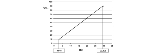
The enablement for the activation of the compressor and the adjustment of the fan speed, depending on the variation in pressure, takes place in this pressure range; the compressor is deactivated above and below these values for safety reasons, to prevent damage to the system.
The pin out for the sensor is illustrated in the diagram below.
|
|
The supply voltage can vary +/- 10% and the operating temperature of the sensor is between 5°C and 80°C |
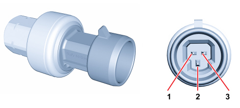
1- Earth
2 - Supply voltage
3 - Output signal
Compressor
This is the central component of the climate control system, which uses the mechanical energy from the engine through a pulley to circulate the refrigerant fluid in the circuit.
Depending on the engine type, the vehicle is equipped with the compressors illustrated below
|
ENGINE TYPE |
COMPRESSOR |
OIL TYPE |
SYSTEM GAS QUANTITY [g] |
|
1.3 Multijet 1.6 JTD 16v |
SANDEN SD6V12 variable capacity |
SP10 |
450 ± 40 |
|
1.4 16v 1.4 16v TJet 1.4 MultiAir 1.4 Turbo MultiAir |
DENSO 5SL12 variable capacity |
ND8 |
450 ± 40 |
Variable capacity compressor specifications
|
Type |
Denso 5SL12 |
Sanden SD6V12 |
|
Maximum capacity |
126.3 cc/rev |
125.1 cc/rev |
|
Minimum capacity |
0 cc/rev |
6.2 cc/rev |
|
Number of cylinders |
5 |
6 |
|
Number of maximum continuous revs |
8000 rpm |
8000 rpm |
|
Number of maximum non continuous revs |
9200 rpm |
9200 rpm |
|
Minimum speed |
700 rpm |
575 rpm |
|
Oil type and quantity |
ND8-80 cc |
SP10-120 cc |
The capacity of these types of compressors may increase or decrease depending on variations in load requested by the system, changing exterior conditions such as temperature and/or humidity and sharp variations in engine load conditions.
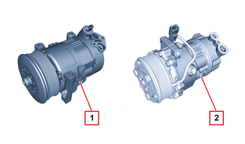
1 - Denso 5SL12
2 - Sanden SD6V12
The adjustment of these compressors is based on the intake pressure value according to the following logic:
- Low pressure, the capacity of the compressor tends towards the minimum value.
- High pressure, the capacity increases.
This adjustment logic refers to the following practical conditions:
- "low intake pressure" means that the load on the climate control system is such that it does not require a high fluid flow rate. Therefore the compressor intake pressure is reduced compared with normal operation and the compressor capacity is reduced.
- "high intake pressure" means that there is an increased load on the climate control system and the amount of coolant fluid required is high. Therefore the compressor intake pressure is higher for normal operating values and the capacity of the compressor increases to increase the flow rate of the fluid in the circuit.
These compressors operate at maximum capacity in normal operating conditions.
Denso 5sl12 compressor
The DENSO 5SL12 is a clutch-less (without magnetic clutch) and variable capacity type compressor. These compressors make it possible to gradually alter the flow rate of the coolant fluid reaching the evaporator.
The adoption of these compressors makes the presence of the frost sensor redundant and it is therefore no longer fitted.
The compressor receives power directly from the crankshaft by means of a poly-v belt.
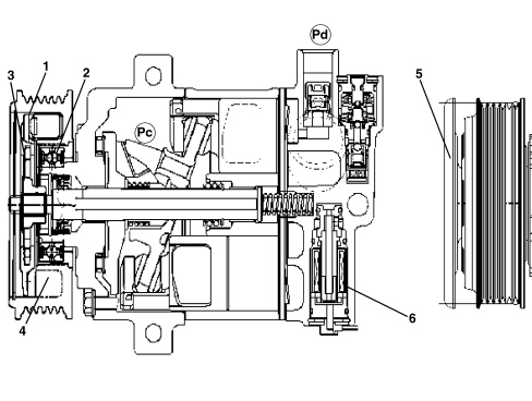
The poly-V belt is wound around the compressor pulley (1).
The pulley is not in one piece with the compressor shaft, but is fitted on it by means of a ball bearing (2).
The pulley drive is also transmitted continuously to the compressor shaft by means of limiters (3) which, in the event of seizing due to a problem with the compressor, stop to prevent the pulley from locking, and thus breaking the auxiliary drive belt.
In order to reduce the torque fluctuations that produce noise, dampers (4) and an inertia mass (5) fixed directly on the shaft are adopted.
As the power is always transmitted to the compressor shaft, the function of switching the compressor on and off is entrusted to the ON/OFF valve (6).
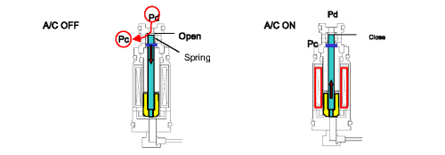
In OFF conditions the valve remains open, allowing the high pressure Pd to enter the regulation chamber, becoming Pc which, thrusting on the pistons, places the capacity at 0.
If the valve is supplied, the passage closes and therefore the regulation system starts to operate like a traditional variable capacity compressor.
The capacity of the 5SL12 type of compressor can vary as a result of:
- variations in the load requested from the system,
- changed outside temperature and/or humidity conditions,
- sharp variations in engine load.
The compressor consists of 5 pistons (1) fixed to an oscillating plate (2). The pistons move inside the cylinders housed in the compressor casing and are moved by the oscillations of the plate. The movement of the plate is produced by the transmission shaft (3).
The latter is rotated by the pulley, consequently by the crankshaft.
The flow rate of the coolant fluid is regulated by altering the capacity of the compressor. This is achieved by varying the angle of the connecting rod holder plate, in other words by altering the piston stroke.
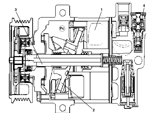
The inclination angle of the plate is determined by the regulating valve (4), which allows the alteration in the pressure inside the compressor casing (Pc) depending on the intake pressure.
In normal operating conditions, the intake pressure (Ps) acting on the diaphragm (1) overcomes the force exerted by the spring (2). The ball (3) closes the flow for the supply pressure (Pd) and the pressure inside the compressor casing (Pc) remains unchanged. The capacity does not alter, in other words it remains at the maximum value.
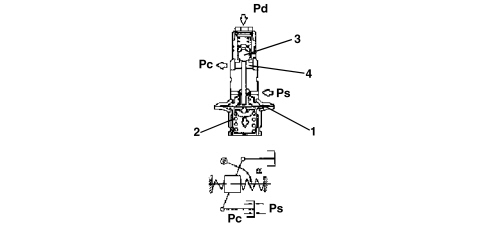
In the case of "low intake pressure" it does not manage to overcome the force of the spring (2), therefore the ball (3) is moved and releases the flow of the supply pressure (Pd). The pressure vent chamber (4) (Pd) is in contact with the inside of the compressor casing: the pressure inside the compressor (Pc) increases.
Under these circumstances (Pc) > (Ps), in other words the pressure acting under the piston skirt is greater than that at the piston crown, means that the connecting rod holder plate tends to reduce its inclination angle, thereby reducing the capacity of the compressor and, consequently, the flow rate.
Sanden sd6v12 compressor
The compressor is directly driven by the crankshaft by means of a Poly-V drive belt.
When the climate control syste is not working, the pulley freewheels on the ball bearing driven by the poly-v belt.The front dics is 0.6 - 0.8 mm away from the pulley. The compressor is therefore inactive.
When the system is turned on, the solenoid is supplied and produces a magnetic field. The resulting force attracts the front disc against the pulley, forming one piece with the joint and consequently the compressor propeller shaft activating rotation.
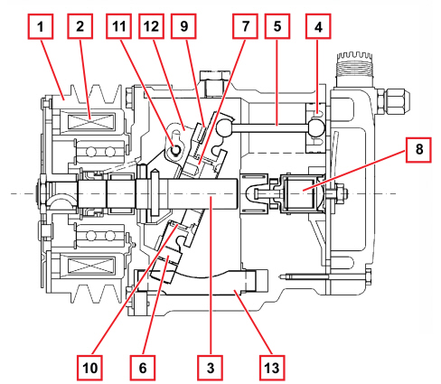
The compressor is caused to rotate by the power unit through the pulley (1) and the electro-magnetic clutch (2).
The compressor propeller shaft (3) causes the rotation of a circular shaped rotor (7). The rotor is not fitted on the shaft, but connected to it by a pin (11) on the shaft which engages with a slotted plate (12) securing to the rotor and the connecting rods (5) for the pistons (4). The rotor - connecting rod carrier plate matching is produced by an axial bearing.
A circular plate, known as a connecting rod carrier (6), is fitted on the rotor hub, to which a radial bearing (10) between the hub rotor and the plate inner seal is fitted, by means of thrust ball bearings (9) fitted between the rotor ring gears and the plate.
In addition to be connected to the rotor, the connecting rod carrier plate is secured to the compressor casing by means of splining on the edge of the ring gear which houses an adjustable bushing made from a low friction material which attaches the end of a slide (13) made from a low friction material. The other end of the slide is inserted in an adjustable housing on the compressor casing.
The alternating movement of the pistons is produced as the result of the inclination of the rotor-connecting rod carrier plate assembly rotation axis in relation to the compressor shaft.
It is necessary to point out that, given the fitting described previously, the connecting rod holder plate does NOT rotate with the rotor, but obtains the oscillating movement produced by the rotation of the rotor in relation to a tilted axis from it.
The inclinatin of the assembly is made possible by the sliding of the shaft pin within the rotor plate slot.
The angle of the plate is determined by a regulation valve (8) according to the difference in pressure between the intake and the supply.
In normal operating conditions, the compressor works at maximum capacity, whilst when the intake pressure is low, the inclination of the plate decreases and there is a reduction in capacity.
Condenser with built-in drier filter
The condenser is a heat exchanger located in front of the engine coolant radiator.
The refrigerant fluid in a gaseous state passes through the condenser pipes and liquefies, on average, at a temperature of 60°C.
The outside air produced by the vehicle moving forwards comes into contact with the condenser. When the vehicle is stationary or driving in traffic, the flow of air is produced by the engine radiator fan.
If the heat exchanger in the condenser is insufficient, this increases the pressure in the system and causes the incomplete condensation of the fluid, reducing the efficiency of the system.
There is a housing on the left side of the condenser for the built-in drier filter. This allows the layout of the system to be improved.
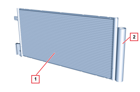
1 - Condenser
2 - Built-in drier filter
Fan
In the manual system the fan is activated by the passenger compartment air speed selector, which sends the signal to a resistive divider which produces the different speeds. The resistive divider is fitted in the duct between the dynamic air intake and the unit to cool it.
In the automatic system the fan is operated by dedicated buttons in the control panel which send the signal to the Climate Control Node which produces different voltage values for the different speeds.
Pollen filter
The pollen filter is designed to filter the outside air entering the passenger compartment.
It is located inside the air conditioner casing.
The filter is fitted on both the manual version and the automatic version of the climate control system.
Additional heater (ptc)
The vehicle may be fitted with an additional heater PTC which is designed to heat the passenger compartment more quickly with the vehicle moving when the outside weather conditions are poor (for example in a particularly cold climate).
It is a resistance located near the radiant mass with a maximum power of 750W.
Operating logic
The additional heater (PTC) is managed by an electronic control unit located at the edge of the climate control unit which activates the ignition relays for at least three seconds consecutively if the following conditions prevail:
- Request for PTC activation from the CAN by the climate control unit (on versions with automatic climate control system) OR fan activation signal and maximum hot request (on versions with manual climate control)
- Outside temperature (< 20 °C)
- Engine speed > 700 rpm
- Engine coolant < 70 °C
- Battery voltage > 12.6 V
The two relays are activated in three steps within 5 seconds:
|
Step |
PTC command |
Time |
|
250 W |
PTC1 = ON - PTC2= OFF |
0s |
|
500 W |
PTC1 = OFF - PTC2= ON |
2.5s |
|
750 W |
PTC1 = ON - PTC2= ON |
5s |
The PTC is deactivated if at least one of the following conditions persists for at least 3 seconds.
- Request for PTC deactivation from the CAN by the climate control unit (on versions with automatic climate control system) or fan deactivation signal and NOT maximum hot request (on versions with manual climate control)
- Outside temperature (> 20 °C)
- Engine speed < 600 rpm
- Engine coolant > 70 °C
- Battery voltage < 11.2 V
Thermal balance
The PTC is disabled in successive steps according to the engine coolant temperature, as shown in the following table:
|
Engine water temperature |
% PTC |
|
> 70 ºC |
0 |
|
> 65 ºC and < 70 ºC |
33 |
|
> 60 ºC and < 65 ºC |
66 |
|
< 60 ºC |
100 |
Electrical balance
The PTC is disabled in steps also depending on the battery voltage as set out in the table below:
Graph for the first 120 seconds from switching on (in which the alternator is still not working at full speed):
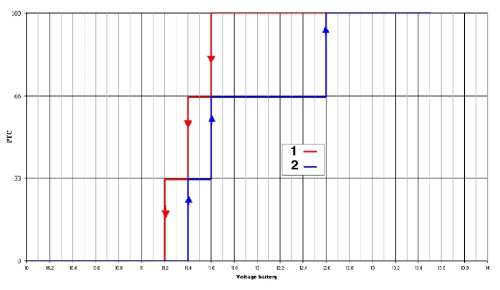
1. PTC operation with decreasing battery voltage
2. PTC operation with increasing battery voltage
Graph after 120 seconds from switching on (in which the alternator is recharging the battery):
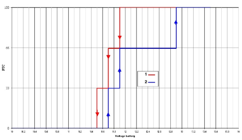
1. PTC operation with decreasing battery voltage
2. PTC operation with increasing battery voltage