SPECIFICATIONS
GENERAL SPECIFICATIONS
The Bosch Motronic ME7.9.10 system with a motorized throttle belongs to the category of ignition systems which have built-in, phased, sequential electronic injection.
The control unit electronically manages the air flow rate at the rotation speed set by the electronic throttle, regulates the fuel injection so that the (air/fuel) ratio is always within optimum values, calculating the moment of ignition, in order to allow the smooth operation of the engine when the environmental parameters and loads applied vary.
The ignition system is static advance with a single coil with three outlets. The power modules are housed inside the control unit.
The self-adaptive engine management system can recognise the changes that take place in the engine. It compensates for them using the self-adaptive functions that correct the fuel mixture and air flow plans mapped in the control unit.
There are two adjustment functions in particular for the carburation dependent on whether the evaporation control solenoid valve is open or closed plus an idle adjustment function: the latter is capable of effectively compensating for any air leaks.
The continuous self-adjustment of the carburation makes it possible to ensure the correct quantity of fuel in all temperature and altitude conditions.
As a result of this, after every intervention it is necessary to drive the vehicle for at least 15 minutes in various operating conditions in order for any changes that have taken place in the system to be memorised in the control unit and to end the adaptation.
The main functions of the system are basically as follows:
-
injection time adjustment;
-
ignition advance adjustment;
-
cold starting check;
-
check on enrichment during acceleration;
-
fuel cut-off during over-run;
-
idle speed management (also dependent on the battery voltage);
-
restriction of the maximum engine speed;
-
control of combustion with Lambda sensor;
-
petrol vapour recovery;
-
fan control;
-
switching the climate control system on/off;
-
self-diagnosis;
-
slider on-off control;
-
continuous variable valve timing control;
-
calculation of the vehicle speed;
-
automatic management of engine starting.
There is also a special function that manages the connection with the body computer via a two-way signal for the CAN line. This includes:
-
engine temperature for instrument panel (output);
-
battery voltage (output);
-
engine rpm (output) for instrument panel;
-
engine overheating warning light for instrument panel (output);
-
engine oil pressure warning light for panel (output);
-
vehicle speed (output) + mileometer (input/output);
-
Alfa code anti-theft device (input/output);
-
key status;
-
consumption signal (output) for trip computer.
-
fuel level signal (input)
Injection system
The basic conditions that must be satisfied in the preparation of the air/fuel mixture for the smooth running of ignition-controlled engines are, basically:
-
the “metering” (air/fuel ratio) must be kept as close as possible to the stoichiometric value to ensure that combustion is quick, avoiding unnecessary fuel consumption
-
the "homogneity" of the mixture, comprising petrol vapours, dispersed in the air as finely and uniformly as possible in order to ensure the stability and efficiency of the catalytic converter over a period of time.
The injection/ignition system uses an indirect measuring system known as the SPEED DENSITY-LAMBDA type.
In other words, the angular rotation, density of the intake air and control of the mixture strength (feedback).
In practice the system uses the ENGINE SPEED (rpm) data and the AIR DENSITY information (pressure and temperature) to measure the quantity of air drawn in by the engine.
In addition to the density of the intake air, the quantity of intake air for each cylinder for each engine cycle also depends on the unitary capacity, volumetric efficiency and supercharging.
Air density refers to the air drawn in by the engine and is calculated according to the absolute pressure and temperature, both of which are measured in the intake manifold.

|
As the engine management system is based on the management of the engine torque, the amount of fuel is calculated taking the factors that determine the increase or decrease into account. |
Volumetric efficiency refers to the parameter relating to the cylinder filling coefficient measured through experiments carried out on the engine for the entire operating range which are then stored in the electronic control unit memory.
Having established the quantity of intake air, the system must provide the correct amount of fuel depending on the desired mixture strength.
The end of injection impulse or supply timing is stored in the control unit memory and varies according to the engine speed and pressure in the intake manifold.
In practice it involves the processing that the electronic control unit carries out to operate the sequential, timed opening of the four injectors, one per cylinder, for the exact amount of time required to produce the air/petrol mixture closest to the stoichiometric ratio.
The fuel is injected directly into the manifold near the inlet valves at a pressure of about 3.5 bar.
The speed (rpm) and the density of the air (pressure and temperature) are used for measuring the quantity of intake air which, when established, is used for metering the amount of fuel needed for the desired mixture strength.
The other sensors in the system (coolant temperature, throttle valve position, battery voltage, etc.) allow the electronic control unit to correct the basic strategy for all the engine operating conditions.
Ignition system
The ignition system is the inductive discharge, static advance type, i.e. there is no high tension distributor with the power modules located inside the injection/ignition electronic control unit.
The primary winding for each coil is connected to the power relay (and is therefore supplied by the battery voltage) and to the electronic control unit pins for connection to earth.
After the starting stage, the electronic unit manages the basic advance taken from special maps dependent on:
-
engine rotation speed
-
absolute pressure value (mmHg) measured in the intake manifold;
-
engine temperature.
The ignition advance is correct, as in the case of the fuel injection, by the torque management strategy.
The spark plugs for the cylinders are connected directly to the coil secondary winding terminals (one per spark plug).
OPERATION
Diagram showing information entering/leaving the control unit
The information entering/leaving the control unit is illustrated in the diagram below.
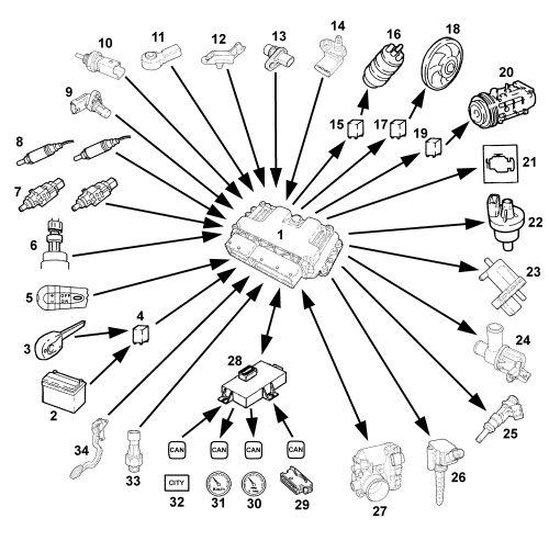
1, Engine management control unit with ambient pressure sensor
2, Battery
3, Ignition switch
4, Engine management system relay
5, Cruise Control lever
6, Linear pressure sensor
7, Brake pedal and clutch pedal switches
8, Lambda sensors upstream and downstream of the converter
9, Timing sensor
10, Engine coolant temperature sensor
11, Detonation sensor
12, Turbo pressure sensor
13, Engine rpm and TDC sensor
14, Intake air temperature and pressure sensor
15, Electric fuel pump relay
16, Fuel pump
17, Radiator fan relay
18, Radiator fan
19, Compressor engagement relay
20, Air conditioning compressor
21, Injection system failure warning light
22, Fuel vapour solenoid
23, Waste gate solenoid
24, Shut-off solenoid
25, Injectors
26, Ignition coils
27, Throttle control actuator and throttle position sensor
28, Body computer (connected to C-CAN)
29, Diagnostic equipment connection (via CAN)
30, Rev counter (via CAN)
31, Speedometer (via CAN and ABS control unit)
32, Power steering button (via CAN)
33, Switch for oil pressure warning light
34, Accelerator pedal sensor
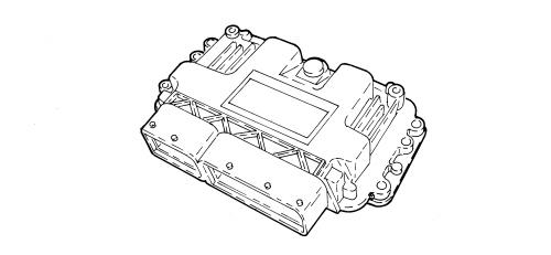
SELF-LEARNING
The control unit implements the self-learning logic under the following conditions:
-
removing-refitting or replacement of the injection control unit
-
removing-refitting or replacing the throttle body
The values stored by the control unit are retained when the battery is disconnected.
SYSTEM SELF-ADJUSTMENT
The control unit is equipped with a self-adaptation function that is designed to recognize the changes that take place in the engine due to the processes of bedding in over a period of time and ageing, both of the components and the engine itself.
These changes are memorized in the form of modifications to the basic map and are designed to adapt the operation f the system to the gradual alterations to the engine and the components compared with the specifications when new.
This self-adjustment function also allows for compensation for the inevitable differences (due to production tolerances) with components that may have been replaced.
From the analysis of the exhaust gases, the control unit modifies the basic map in relation to the specifications of the engine when new.
The following self-adaption strategies are provided in the control unit:
- mixture strength control multiplication coefficient; takes into account the mixture strength slips linked to the sensor differences, injectors, air chamber and continually updates while the engine is running.
- mixture strength control additive coefficient, corrects injector leaks and updates when idling.
The self-adjustment parameters are not deleted when the battery is disconnected.

AUTODIAGNOSIS AND RECOVERY
The control unit auto-diagnostic system checks that the system is working properly and signals any irregularities by means of an MIL warning light in the instrument panel with a standardised icon and colour, as laid down by European regulations.
This warning light indicates engine management faults and also faults detected by EOBD diagnostic strategies.
The MIL warning light operating logic is as follows.
The warning light comes on with the ignition on and remains on until the engine is started up; the control unit autodiagnostic system checks the signals coming from the sensors and compares them with the permitted data limits.
Siganalling of faults during engine starting:
-
the failure of the warning light to go out when the engine has been started indicates that there is an error memorized in the control unit.
Signalling of faults during operation:
-
the warning light comes on in flashing mode to indicate possible catalytic converter damage due to misfiring.
-
the warning light comes on in constant mode to indicate the presence of engine management or EOBD diagnostic errors.
The control unit defines the recovery settings on each specific occasion according to which components are faulty.
The recovery parameters are managed by non-faulty components.
The recovery strategies that can be activated from the control unit are:
- limp home following throttle body error
- limp home following accelerator pedal error
- turbocharging; the throttle is closed when there is a rise in the turbocharging pressure during the transient stages of acceleration with the target pressure and the measured pressure differential greater than 200 mbar, while a turbocharging pressure limit is activated if there is an error with the accelerator pedal or throttle actuator.
European regulations require the EOBD system to use the following strategies relating to the engine subsystems that have a direct impact on emissions:
- fuel supply system (fuel system diagnosis), to detect any malfunctions on the fuel line.
- Lambda sensor diagnosis to detect operating errors in the sensor upstream of the catalytic converter.
- catalytic converter diagnosis to detect deterioration via indirect measuring of the oxygen storage capacity.
- diagnosis relating to irregular ignition (misfire diagnosis) that stops the catalytic converter working correctly, potentially causing irreversible damage.

SYSTEM CONTROLS AND MANAGEMENT
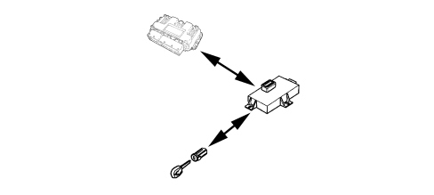
Alfa code recognition
The moment the control unit receives the key ON signal it converses with the body computer to obtain the go ahead for starting.
|
|
The starter motor is controlled directly by the key and not by the control unit. |
The communication takes place through the CAN line.
|
|
As in the last example, the W recovery line is not used again. |
Cold starting check
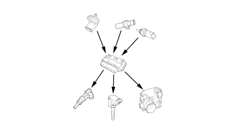
The following occurs in cold starting conditions:
-
a natural weakening of the mixture (as a result of the poor turbulence of the particles of fuel at low temperatures)
-
the reduced evaporation of the fuel
-
condensation of the fuel on the internal walls of the intake manifold
-
greater viscosity of the lubricant oil.
The electronic control unit recognizes this condition and corrects the basic injection time according to the:
-
engine coolant temperature
-
intake air temperature
-
battery voltage
-
engine rpm.
The ignition advance only depends on the engine coolant temperature and speed.
Below a threshold that can be calibrated (from approx 15 °C to approx - 25 °C) the ignition is enabled in "multispark" mode.
This strategy, achieved by controlling the coils to obtain a quick series of sparks, facilitates combustion of the mixture.
The rotation speed decreases proportionally as the engine temperature increases until the nominal value is reached when the engine is warmed up.
Combustion - lambda sensor check
In EOBD systems the Lambda sensors, which are all the same type, are fitted upstream of the catalyzer system and downstream of the catalyzer.
The pre-converter sensor controls 1st loop mixture strength (upstream sensor closed loop).
The post-converter sensor is used for the fault diagnosis of the converter and for modulating the 1st loop control parameters.
The second loop is therefore adaptive to make up for production discrepancies and slight drift that pre-converter sensor responses could experience due to ageing and contamination.
This control is known as 2nd loop control (post-converter sensor closed loop).
The control of the mixture strength in the first loop is activated when the pre-converter Lambda sensor is capable of providing an expected signal which takes place a while after the engine has been started.
Sensor activation time depends on the initial temperature of the engine.
Control of the second loop is activated with a much higher temperature than that of the first loop: if the control of the first loop takes place 80 seconds after the engine has been started, the control of the second loop takes place after 450 seconds.
|
|
Post-converter sensor voltage is around 630 mV and is constant (when it starts to fluctuate the converter is worn). |

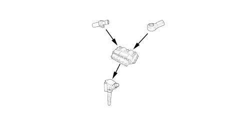
Detonation control
The control unit detects the presence of detonation (engine knock) by processing the signal coming from the appropriate sensor.
The contol unit continuously compares the signals coming from the sensor with a reference value which is, in turn, constantly updated in order to take into account background noise and the ageing of the engine.
The control unit is therefore capable of detecting the presence of detonation (or the onset of detonation) in each individual cylinder and reduces the ignition advance in the cylinder concerned (in steps of 3 degrees up to a maximum of 6 degrees) until the phenomenon has disappeared. Later on, the advance is gradually restored to the basic value (in steps of 0.8°).
During acceleration, a higher threshold is used to take into account the increased engine noise in these circumstances.
The detonation control logic also has a self-adjustment function which memorises the reductions in the advance that are continuously repeated in order to adapt the map to the different conditions that may affect the engine.
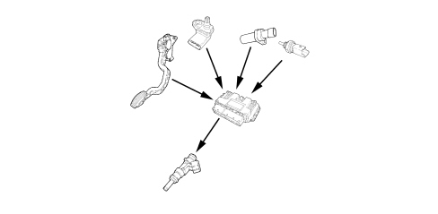
Check on enrichment during acceleration
During this stage, the control unit suitably increases the amount of fuel supplied to the engine (to produce maximum torque) according to the signals coming from the following components:
-
accelerator pedal potentiometer and throttle position.
-
rpm and TDC sensor
The basic injection time is multiplied by a coefficient depending on the temperature of the engine coolant, the opening speed of the accelerator throttle and the increase in pressure in the intake manifold.
If the sharp variation in the injection time is calculated when the injector is already closed, the control unit reopens the injector (extra pulse) in order to compensate the mixture strength as quickly as possible; the subsequent injections are aleady increased on the basis of the coefficients mentioned previously.
|
|
ASR and VDC management requires the control unit to reduce the torque and therefore the ignition time together with action on the throttle and on the ignition advances. |
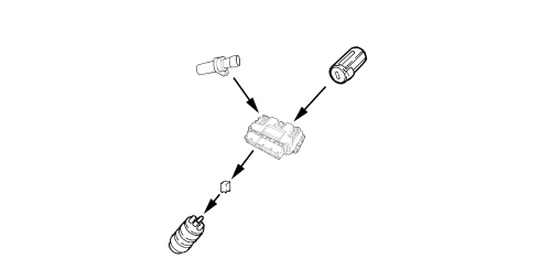
Fuel supply - electric fuel pump check
The control unit supplies the electric pump:
-
with the ignition ON for 0.8 secs.
-
with the ignition in the starting position AVV and the engine speed > 20 rpm.
The control unit interrupts the supply to the electric pump:
-
with the ignition OFF.
-
with the engine speed < 40 rpm.
The fuel supply system with recirculation ensures a constant pressure differential of 3.5 bar.
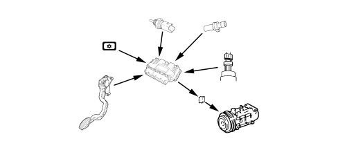
Connection with climate control system
The climate control system is constantly managed by adding together the torque required by the user and the torque required for the operation of the compressor:
- when the total is less than the calibrated threshold, depending on the engine rpm, the user request is enabled;
- when the total is more than the calibrated threshold, depending on the engine rpm and the speed being below 10 km/h, the user request is not enabled.
The control unit momentarily interrupts the supply to the compressor:
-
during starting
-
switching it off when the engine temperature > 115 °C and reactivating it with a hysteresis of 5.3 °C.
-
during take off with the accelerator pedal fully depressed.
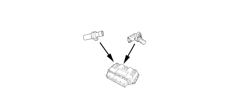
Recognition of cylinder position
The engine timing signal, together with the engine rpm and TDC signal, allow the control unit to recognize the succession of cylinders to implement the timed injection.
This signal is produced by a Hall effect sensor, located on the cylinder head near the flywheel on the inlet camshaft.
Fuel cut-off during overrun
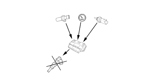
When the accelerator pedal is released and beyond a pre-set engine speed level, the control unit:
-
cuts off the supply to the injectors
-
reactivates the supply to the injectors at 1200 rpm in first gear and at 1000 rpm in other gears.
If the supply fails, the number of revs decreases more or less quickly depending on the driving conditions.
Before the idle speed is reached the progress of the engine speed decrease is checked.
If it is above a certain figure, the fuel supply is partly reactivated to ensure the “gentle accompaniment” of the engine to the idle speed.
The levels for reintroducing the fuel supply and fuel cut off vary according to the:
-
engine coolant temperature
-
vehicle speed
-
engine rpm.
Fuel vapour recovery
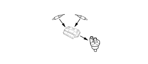
The (pollutant) fuel vapours, collected in an active charcoal filter (canister), are sent to the intake ducts to be burnt.
This takes place by means of a solenoid valve which is only operated by the control unit when the engine operating conditions allow it.
The control unit compensates for this additional amount of fuel with a reduction in the delivery to the injectors.
Maximum rpm check
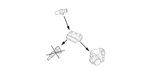
The control of the maximum number of revs is carried out by the control unit, limiting the engine torque through the motorized throttle.
The first action the control unit takes is to cut off the supply of fuel adjusting the injection times and, if this is not sufficient, closing the motorized throttle.
The maximum number of revs for the 120 bhp version is 6350.
The maximum number of revs for the 155 bhp version is 6500.
Injection time adjustment
The control unit calculates the injector opening time and controls them extremely quickly and precisely on the basis of the:
-
engine load (rpm and air flow rate)
-
battery voltage
-
engine coolant temperature.
The air flow rate is calculated by taking into consideration the parameters recorded by the air temperature and pressure sensor fitted on the air chamber. Air pressure entering the throttle body and the ambient pressure via the sensor on the control unit are also corrective factors in the calculation of the flow.
The injection is the sequential, phased type for each cylinder and takes place at the optimum start of injection point whilst the end of injection point is fixed.
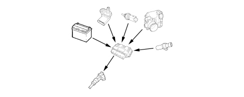
Ignition advance adjustment;
Thanks to a map stored in the control unit memory it is capable of calculating the ignition advance according to:
-
the engine load (minimum, partial, full, according to the rpm and air flow rate)
-
intake air temperature
-
engine coolant temperature.
The ignition can be selectively delayed at the cylinder required, recognized through the combination of the value recorded by the rpm sensor and the “timing” data.
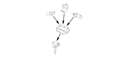
Idle speed check
The control unit recognizes the idle condition through the accelerator pedal in the released position.
To check the idle speed, depending on the consumers switched on and the brake-clutch pedal signals, the control unit controls the position of the motorized throttle.
The idle speed when warm is 750 ± 50 rpm.
On the basis of an electrical balancing strategy, the control unit increases the idle speed when the battery voltage is reduced to the calibrated threshold value.
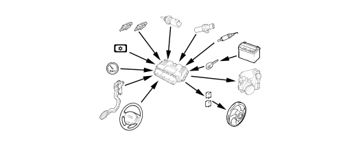
Radiator cooling fan check
Depending on the temperature of the coolant, the control unit switches on the fan:
-
1st speed engagement temperature 97°C
-
2nd speed engagement temperature 102°C
There is then a further check (linear pressure sensor signal) which switches on the fan at the 1st or 2nd speed depending on the pressure of the refrigerant gas when the air conditioning system is switched on.
If there is no coolant temperature signal, the control unit implements the recovery function switching on the fan at the 2nd speed until the error disappears.
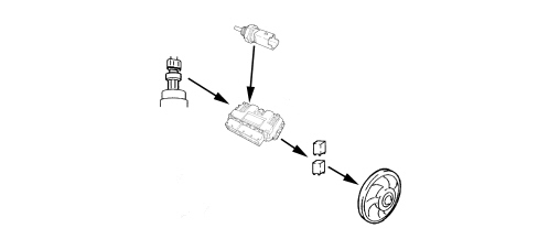
Engine starting
During starting the control unit measures the engine temperature and establishes the injection time and the suitable ignition advance.
Above a threshold of 20 rpm and with engine timing detected, the control unit controls the injectors and the coils in timed sequence to reduce unburnt hydrocarbon exhaust emissions.
If the engine will not start, the control unit reduces the amount of fuel using a multiplication factor in order to reduce the possibility of flooding the engine.
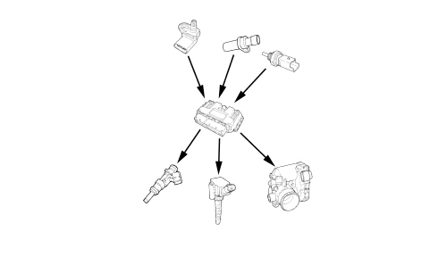
Torque control
The control unit for managing the various operating strategies is mainly based on control of engine torque.
There are two torque delivery rules:
- torque delivery with mechanical rule, for high engine loads, in practice when the measured throttle position is greater than the full load position (95% of load)
- torque delivery with controlled rule (this mode is used when mixture strength control is activated).
The control unit detects the torque request via the accelerator pedal and, after having made its calculations, adjusts the ignition advances, the throttle opening and the injection times.
There are three main tables for calculating the engine torque:
- low loads calculation table
- high loads calculation table
- reverse gear calculation table.
For the 155 bhp version only, when the dynamic function is activated another three calculation tables are taken into consideration, namely:
- low load with dynamic function activated calculation table
- heavy load with dynamic function activated calculation table
- reverse gear with dynamic function activated calculation table.
|
|
The dynamic function can be activated via the DNA "manettino" dial described later on. |
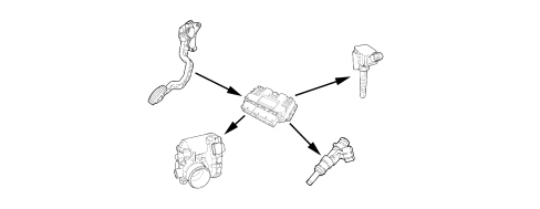
Car handling
The handling strategy includes three actions carried out by the control unit to make longitudinal fluctuations caused by the dynamics of the vehicle during transistions smoother and more gradual in order to make the use of the car as comfortable as possible.
|
|
Transitions refer to acceleration and deceleration of varying suddeness, due to the action on the accelerator pedal and gear changes. |
The control unit detects the acceleration and deceleration transient stages via the accelerator sensor and the clutch and brake pedal switches, therefore intervening in torque management via the TIP-UP and TIP-DOWN calculation modules
Depending on the situation, the control unit sets a fast torque control, adjusting the ignition advances and, if this is not enough, it activates a slow torque control adjusting the opening of the throttle and consequently the injection times.
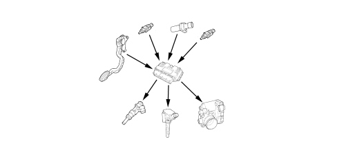
Turbocharging control
Turbocharger pressure management
The control unit controls the engine torque directly taking turbocharging into account, operating the waste gate valve directly to achieve the target pressure in the intake manifold depending on:
- engine load
- ambient pressure
- turbocharger pressure.
In particular, when the desired pressure reaches a calculated threshold, the control unit starts to adjust the exhaust gas flow through the waste gate. This introduces a feedback that guarantees system stability.
As well as the desired pressure, the power supplied to the compressor to achieve it is calculated. This power must be supplied from the turbine and therefore the exhaust gas flow is regulated to guarantee that this power is reached.
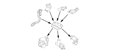
Shut-off solenoid valve management
In systems with a turbocharger, when the throttle is closed quickly (in overrun) excess pressure is produced in the duct upstream of the throttle. This tends to slow the compressor impeller, leading to strong vibrations and noise.
The shut-off valve allows the recirculation of the air from downstream to upstream of the compressor, reducing the pressure in the manifold.
The control unit directly controls the shut-off valve depending on:
- engine load
- atmospheric pressure
- turbocharger pressure.
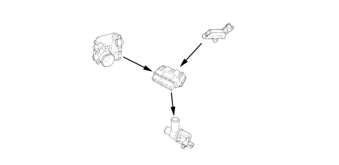
Control of NORMAL / DYNAMIC function - 155 bhp version only
Using the DNA "manettino" dial (Dynamic-Normal-All weather), in addition to the differentiated management of the electric steering and the VDC functions, the OVERBOOST function can also be turned on.
The DNA "manettino" dial is connected via discreet line to the Body Computer node, therefore the information concerning the programme selected is made available to the Engine Management Node via the C-CAN.
To manage the OVERBOOST function the Engine Management Node mainly takes into account the position of the accelerator pedal and consequently acts on the waste gate valve regulating the pressure of the turbocharger and adjusting the motorized throttle opening.
With the dynamic function engaged, the maximum torque condition (OVERBOOST) remains activated for a maximum of 80 seconds.
The important specifications of the Normal/Dynamic functions are described below.
Normal/All weather function on
- maximum torque 201 Nm at 5000 rpm
- maximum power 155 bhp
- soft driving strategy
- contained consumption at high engine loads.
Dynamic function
- maximum torque 230 Nm at 3000 rpm
- maximum power 155 bhp
- sporty driving strategy
- higher consumption at high engine loads.
|
|
The management of the OVERBOOST should not be understood as a pressure causing damage to the turbine, but as the possibility of providing greater pressure than the maximum at that moment. |
|
|
The operation of the DNA "manettino" dial is described later on. |
Supercharging recovery
During the supercharging pressure increase in acceleration transitions, if the difference between the target pressure and the pressure measured is more than 200 mbar the throttle is closed.
If there is an error at the accelerator pedal or the throttle actuator a supercharging pressure restriction is activated.
In order to guarantee the protection of the turbocharger the engine management control unit evaluates the temperature of the exhaust gases, using a mapped calculation model, because an excessive increase could cause damage to the turbine.
Cruise control
Depending on the position of the cruise control lever, the control unit directly manages the quantity of fuel injected in order to control and maintain the vehicle speed which has been memorised.
A warning light on the control panel, activated by the control unit, indicates system operation or deactivation status.
For Cruise Control operation
See descriptions 5580A CRUISE CONTROL SYSTEM
ME 7.9.10 INJECTION-IGNITION CONTROL UNIT
Specifications
The control unit is fitted in the engine compartment on the flame bulkhead.
The control unit memory is the flash EPROM type, i.e. it can be reprogrammed from the outside without operations to the hardware.
The self-learning procedure must be carried out if the injection control unit or the throttle casing needs replacing.
Control unit pin out
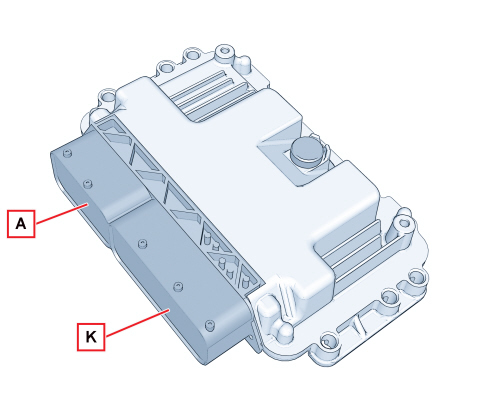
Engine side connector A
1, Lambda sensor heater control (-) downstream of converter
2, Cylinder no. 3 injector control (-)
3, Fuel vapour solenoid control (-)
4, Cylinder no. 2 injector control (-)
5, Shut-off valve control (-)
6, Not connected
7, Not connected
8, Not connected
9, +5V power supply for turbo pressure sensor and intake air pressure/temperature sensor
10, +5V power supply for motorized throttle potentiometers
11, +5V power supply for timing sensor
12, Timing sensor signal
13, Motorised throttle potentiometer reference earth
14, Not connected
15, Not connected
16, Lambda sensor heater control (-) upstream of converter
17, Cylinder no. 1 injector control (-)
18, Waste gate turbo pressure solenoid control (-)
19, Cylinder no. 4 injector control (-)
20, Not connected
21, Turbo pressure sensor signal
22, Motorised throttle potentiometer signal
23, Not connected
24, Intake air temperature signal
25, Intake air pressure signal
26, Not connected
27, Not connected
28, Timing sensor reference earth
29, Engine temperature sensor reference earth
30, Not connected
31, Ignition coil control cylinder 1
32, Not connected
33, Not connected
34, Not connected
35, Engine oil pressure switch
36, Detonation sensor earths
37, Rpm sensor (-)
38, Rpm sensor (+)
39, Not connected
40, Not connected
41, Not connected
42, Motorised throttle potentiometer signal
43, Engine temperature sensor signal
44, Turbo pressure sensor and air pressure/temperature sensor reference earth
45, Not connected
46, Ignition coil control cylinder 3
47, Ignition coil control cylinder 4
48, Ignition coil control cylinder 2
49, Motorised throttle actuator power supply (+)
50, Motorised throttle actuator power supply (-)
51, Detonation sensor signal
52, Lambda sensor reference earth upstream of the converter
53, Lambda sensor signal downstream of the converter
54, Lambda sensor earth downstream of the converter
55, Lambda sensor signal upstream of the converter
56, Not connected
57, Not connected
58, Not connected
59, Not connected
60, Not connected
Vehicle side "K" connector
1, Engine system earth on battery negative
2, Engine system earth on battery negative
3, 12V power supply from F17 (10A)
4, Engine system earth on battery negative
5, 12V power supply from F17 (10A)
6, 12V power supply from F17 (10A)
7, Linear pressure sensor reference earth
8, Not connected
9, Not connected
10, Not connected
11, Air conditioning compressor relay feed
12, Engine cooling fan 2nd speed relay feed
13, Engine cooling fan 1st speed or one speed relay feed
14, Engine cooling fan relay control 3rd speed or PWM
15, Not connected
16, Not connected
17, Not connected
18, Not connected
19, Not connected
20, Not connected
21, Not connected
22, Not connected
23, Not connected
23, Not connected
24, Not connected
25, Not connected
26, Not connected
27, Accelerator pedal 2 potentiometer 5V power supply
28, Linear pressure sensor 5V power supply
29, Accelerator pedal 2 potentiometer reference earth
30, Accelerator pedal 1 potentiometer reference earth
31, Starter motor relay
32, Not connected
33, Alternator (D+) signal
34, Not connected
35, Not connected
36, Not connected
37, Not connected
38, Not connected
39, Not connected
40, Not connected
41, Not connected
42, Not connected
43, Not connected
44, Not connected
45, Not connected
46, Not connected
47, Not connected
48, Not connected
49, Accelerator pedal 1 potentiometer 5V power supply
50, Not connected
51, Not connected
52, Not connected
53, Not connected
54, Not connected
55, Signal from accelerator pedal 2 potentiometer
56, Not connected
57, Linear pressure sensor signal
58, Not connected
59, Not connected
60, Not connected
61, Clutch pedal switch
62, Not connected
63, Not connected
64, Not connected
65, Not connected
66, Not connected
67, Not connected
68, Fuel pump relay feed
69, Not connected
70, Positive power supply from F18 (10A)
71, MIL warning light control
72, Engine management system main relay feed
73, Not connected
74, Not connected
75, Not connected
76, Not connected
77, Not connected
78, Not connected
79, Signal from accelerator pedal 1 potentiometer
80, Not connected
81, Not connected
82, Not connected
83, Not connected
84, Reversing light switch
85, Not connected
86, Not connected
87, Brake light switch signal
88, C-CAN-L terminal CAN
89, C-CAN-H CAN
90, Not connected
91, Not connected
92, Not connected
93, Not connected
94, Not connected
"DNA" VEHICLE DYNAMIC CONTROL (155 bhp version only)
The Alfa DNA system is a device that acts on the vehicle dynamic control systems and is electrically connected to the Body Computer which notifies the nodes involved of the configuration selected.
Engine management control unit
The accelerator pedal is more or less reactive depending on the Alfa DNA system mode. There is an OVERBOOST effect in Dynamic mode.
Instrument panel
The display shows specific information consistent with the mode selected (e.g.: turbo pressure in dynamic mode).
VDC system
The VDC has three settings for each of the three Alfa DNA system positions (e.g.: in dynamic mode the intervention of the VDC is delayed to allow a more active driving style; in all weather mode braking on surfaces with differentiated grip is improved).
Steering
The steering is more or less stiff depending on the mode selected via the "DNA".
Suspension
Where fitted, the active suspension comply with the mode chosen via the DNA selector. For example, in dynamic mode it becomes stiffer, improving handling.
Gearbox
Where an automatic transmission is fitted, the gear change takes place at a higher engine speed and the Alfa DNA system also reduces the change time.
Operation
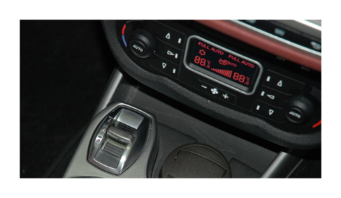
The "manettino" dial is a lever which always remains in the middle position. The configuration selected is recognized by the corresponding LED being lit up or the display in the control panel as illustrated below:
Dynamic display
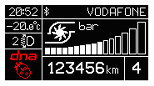
All weather display
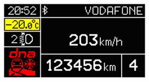
Normal display
No symbol is shown in the display for this configuration.
To turn the dynamic mode on, move the lever forwards (corresponding to the letter "D"), stay in this position for half a second until the LED lights up or the words "Dynamic on" appear in the control panel.
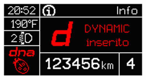
When the lever is released it will return to its middle position.
To return to Normal mode from Dynamic mode, repeat the same movement for the lever with the same time scales, but in this case the LED for the Normal position will light up and the control panel will show "Normal on" in the display.
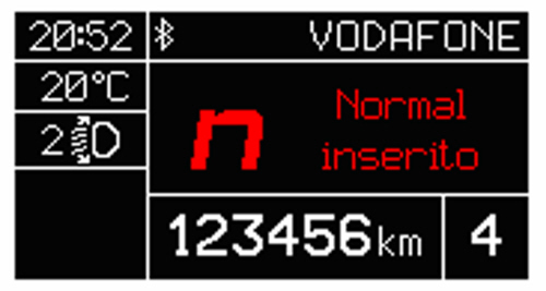
To engage the All weather mode, move the lever backwards (to position A), stay in this position for half a second or until the LED lights up and the control panel shows "All weather on" in the display.
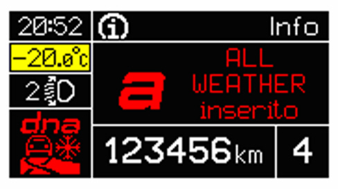
The procedure to return to Normal is the same as the one described for Dynamic.
It is not possible to go directly from Dynamic mode to All Weather mode and viceversa. It is always necessary to return to the Normal mode.
If Dynamic mode was on before a key-off, then the configuration will automatically return to Normal mode at the next key-on.
If, on the other hand, the All weather or Normal mode was engaged, the configuration will be maintained at the next key-on.
The Dynamic mode can only be engaged at speeds below 110 km/h and remains on beyond this speed.
If there is a DNA system or selector failure, no configuration can be engaged and the message "mode not available" will be shown in the panel display.
INJECTORS
Specifications
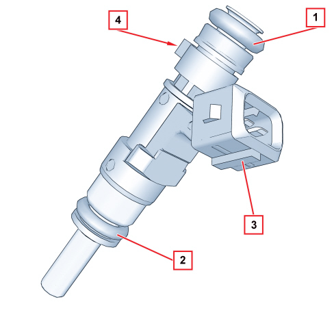
The twin jet injectors (with the spray inclined in relation to the injector axis) are specially designed for engines with 4 valves per cylinder and make it possible to direct the jets towards the two inlet valves.
The injector is the top-feed type with the fuel supply in the top part of the casing which also houses the electrical winding connected to the connector (3) terminals.
When the current passes through the winding, the magnetic field produced attracts the shutter causing the opening of the injector and the flow of fuel.
Two seals ensure the seal on the fuel manifold side (1) and on the intake manifold side (2).
A reference (4) determines the angular position of the injector and the correct direction of the jets in relation to the inlet valves.
|
|
Inspection of the jets will show different openings, in total 10 divided into 2 sections of 5, in practice there are 10 small diffusion cones that together make 2 diffusion cones directed to the 2 intake valves. |
Electrical properties
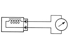
The injector resistance can be measured by disconnecting the connector and connecting an ohmmeter as illustrated.
Resistance value: 14.5 ±5% ohm.
Electrical connections

Pin 1, +12V power supply
Pin 2, Control to earth from control unit
Operation
The jets of fuel at a differential pressure of 3.5 bar come out of the injector and are instantly atomized forming two cones.
The injector operating logic is the sequential, phased type, in other words the four injectors are controlled in accordance with the engine cylinder inlet sequence whilst the supply can already commence for any cylinder in the expansion stroke until the inlet stroke has already started.
The amount of fuel injected depends on the shutter opening time which, in turn, depends on the solenoid supply time.
This time, known as the injection time, is calculated by the control unit in the different engine operating conditions.
FUEL MANIFOLD
The fuel manifold, which distributes the fuel to the injectors, incorporates the seats for the injectors and the differential pressure regulator.
The fuel supply and return are carried out through rapid attachment.
The pressure regulator ensures the right fuel supply pressure depending on the air chamber pressure.
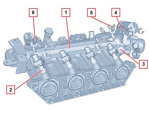
1, Fuel manifold
2, Injector
3, Differential pressure regulator
4, Air pipe
5, Connector for fuel return rapid connector to the tank
6, Connector for fuel supply rapid connector
ENGINE COOLANT TEMPERATURE SENSOR
Specifications
It is fitted on the thermostat and measures the temperature of the coolant by means of an NTC thermistor with a negative resistance coefficient.
The variation in the resistance depending on the temperature is illustrated in the table below.
|
°C |
O |
|
-20 |
15971 |
|
-10 |
9620 |
|
0 |
5975 |
|
10 |
3816 |
|
20 |
2502 |
|
25 |
2044 |
|
30 |
1679 |
|
40 |
1152 |
|
50 |
807 |
|
60 |
576 |
|
70 |
418 |
|
80 |
309 |
|
90 |
231 |
|
100 |
176 |
Electrical properties
- Power supply: 5V
- Maximum current: 2.5 mA
- Maximum power at 25 °C: 15 mV

Pin 1, Signal
Pin 2, Earth
Operation
The reference voltage for the NTC element for the injection system is 5 Volt, because the input circuit in the control unit has been designed as a tension divider, this voltage is divided between a resistance in the control unit and the sensor NTC resistance.
As a result, the control unit is capable of evaluating the sensor resistance variations by means of the changes in voltage and thereby obtaining temperature information.
Composition
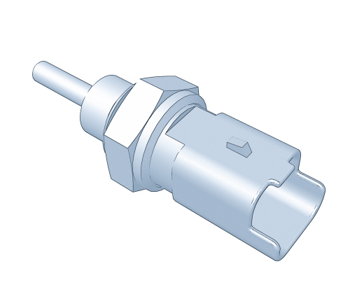
The composition of the sensor is illustrated in the diagram below
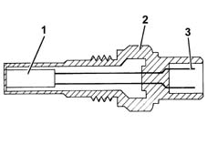
1, NTC resistance
2, Sensor casing
3, Electrical connector
DETONATION SENSOR
Specifications
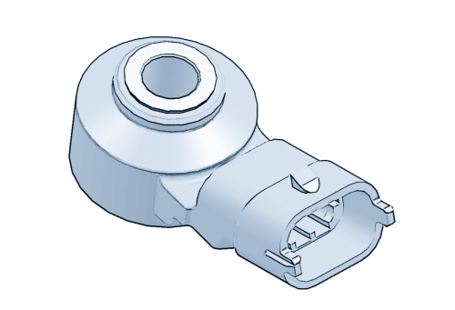
The detonation sensor is the piezoelectric type and is fitted on the crankcase to detect the intensity of the vibrations caused by detonation in the combustion chambers.
The phenomenon produces a mechanical repercussion on a piezoelectric crystal that sends a signal to the control unit and, on the basis of this signal, the control unit reduces the ignition advance until the phenomenon disappears. Later on, the advance is gradually restored to the basic value.
Electrical specifications: resistance 4.9 MΩ ± 20%.
Electrical connections
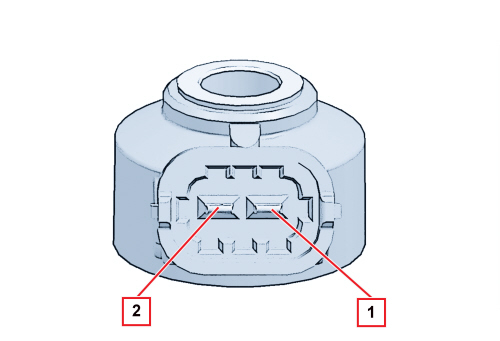
Pin 1, Signal
Pin 2, Earth
Operation
The molecules of a quartz crystal are affected by electrical polarization.
In rest conditions (A) the molecules are not arranged in a particular way.
When the crystal is subjected to pressure or to an impact (B), the higher the pressure, the more marked their arrangement.
This arrangement produces a voltage at the ends of the crystal.
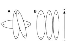
A. Rest position
B. Position under pressure
RPM SENSOR
Specifications
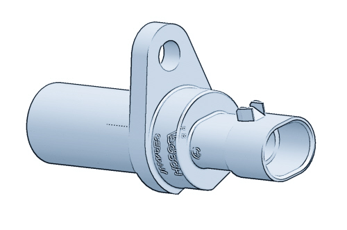
It is fitted on the crankcase front cover facing the phonic wheel built into the crankshaft pulley.
It is the inductive type, in other words it operates through the variation in the magnetic field produced when the flywheel teeth (60 – 2) pass by.
The injection control unit uses the rpm sensor signal for:
-
determining the rotation speed
-
determining the angular position of the crankshaft.
Electrical specifications: resistance 1134 - 1386 Ω at 20°C.
The recommended distance (gap), between the end of the sensor and flywheel, to produce correct signals, should be between 0.5 and 1.5 mm.
Composition
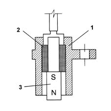
The sensor consists of a tubular casing (1) containing a permanent magnet (3) and an electrical winding (2).
Operation
As a result of the flywheel teeth passing, the magnetic flow created by the magnet (3) fluctuates because of the variation in the gap.
These fluctuations produce an electro-motive force in the winding (2) where an alternately positive (tooth facing the sensor) and negative (gap facing the sensor) voltage is created.
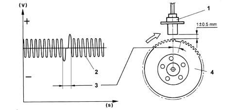
1, Sensor
2, Output signal
3, Signal corresponding to two missing teeth
4, Crankshaft pulley with phonic wheel
All things being equal, the peak sensor output voltage value depends on the distance between the sensor and the tooth (gap).
There are sixty teeth on the flywheel, minus two which have been removed to create a reference: the passage of the wheel therefore corresponds to an angle of 6° (360° divided by the 60 teeth).
The synchronism point is recognized at the end of the first tooth after the space for the two missing teeth: when it passes under the sensor; the pair of pistons 1-4 are 114° before TDC.
Electrical connections

Pin A, Signal +
Pin B, Signal -
TIMING SENSOR
Specifications
The Hallf effect type sensor is used by the injection control unit in conjunction with the rpm and TDC signal to recognize the position of the cylinders and determine the injection and ignition point.
The timing sensor is located on the camshaft housing in the dedicated housing and is opposite the inlet side camshaft.
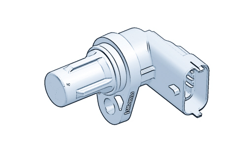
A current-carrying semiconductor layer immersed in a normal magnetic field (force lines at right angles to current direction) generates a potential difference known as a Hall voltage at its terminals.
If current intensity remains constant, the generated voltage depends on magnetic field intensity alone. Periodic changes in magnetic field intensity are sufficient to generate a modulated electrical signal with frequency proportional to the speed of magnetic field change.
The distance between the sensor and the flywheel on the inlet cam axis is altered to produce this change and the reference mark for the timing is used in the process.
Electrical properties
Supply voltage: 5V +/- 10%
Maximum voltage: 16V
|
|
The sensor receives a direct power supply from the injection control unit. |
Electrical connections
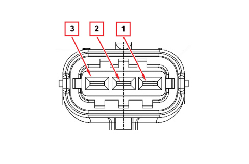
Pin 1, Earth
Pin 2, Signal
Pin 3, 5V power supply
ACCELERATOR PEDAL POTENTIOMETER
Specifications
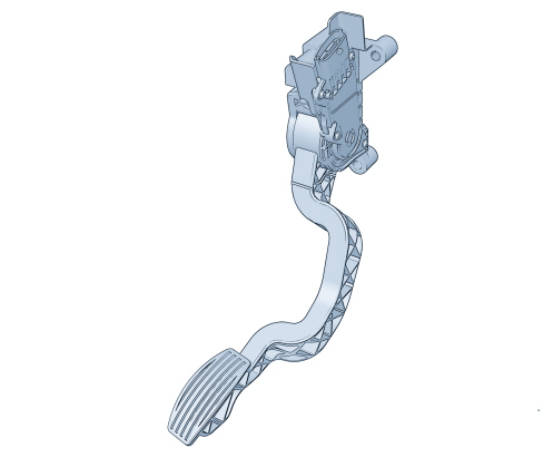
The accelerator pedal is equipped with two built-in potentiometers:
-
one main one
-
one safety one.
The injection control unit implements the following recovery strategies under the following conditions:
-
if one of the two potentiometers fails, the control unit uses the remaining track without restricting the torque and checks the plausibility with the brake switch.
-
if both potentiometers fail completely, throttle opening is prevented.
Operation
The sensor consists of a casing, fastened to the accelerator pedal support which contains a shaft connected to the twin track potentiometer in an axial position.
A coil spring on the shaft guarantees the correct resistance to pressure whilst a second spring ensures the return on release.
Electrical connections
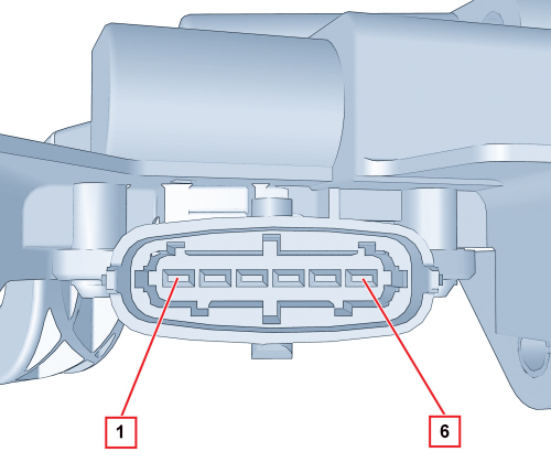
Pin 1, 5V power supply potentiometer 2
Pin 2, 5V power supply potentiometer 1
Pin 3, Potentiometer earth 1
Pin 4, Potentiometer signal 1
Pin 5, Potentiometer earth 2
Pin 6, Potentiometer signal 2
THROTTLE BODY
Specifications
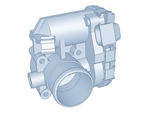
It is fitted on the intake chamber and regulates the quantity of air drawn in by the engine.
Depending on the signal coming from the accelerator pedal potentiometer, the injection control unit controls the opening of the throttle by means of a direct current motor incorporated in the throttle casing.
The opening of the throttle takes place between 0° and 80° thereby including the adjustment of the idle speed.
The throttle casing is fitted with two potentiometers incorporated in such a way that one controls the other and viceversa.
If there is a failure with the two potentiometers or a supply failure, depending on the position of the accelerator pedal, the control unit reduces the engine torque:
-
fully depressed, it cuts off the supply to one or more pistons until a maximum speed of 2500 rpm is reached
-
in the intermediate positions, it cuts off the supply to one or more pistons until a speed of below 1200 rpm is reached
The self-learning procedure must be carried out if the injection control unit or the throttle casing needs replacing.
Operation
The injection control unit operates the motorised throttle according to accelerator pedal requests; a potentiometer connected to it sends a voltage signal to the control unit where it is processed and opening laws are produced.
Electrical connections
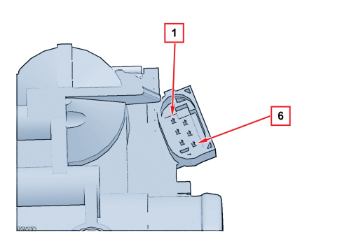
Pin 1, Throttle opening motor earth
Pin 2, TPS1 and TPS2 potentiometer earth
Pin 3, TPS1 and TPS2 potentiometer 5V positive
Pin 4, Throttle opening motor positive
Pin 5, TPS2 potentiometer signal
Pin 6, TPS1 potentiometer signal
INTAKE AIR TEMPERATURE AND PRESSURE SENSOR
Specifications
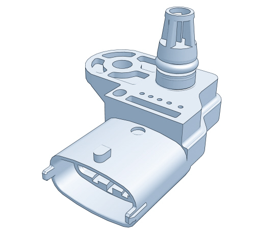
The intake air temperature and pressure sensor is an integrated component that has the function of measuring the pressure and the temperature of the air inside the intake manifold.
Both pieces of information are needed by the control unit to define the quantity of air drawn in by the engine; this information is then used to calculate the injection time and the ignition point.
The sensor is fitted to the air chamber
Composition
The air temperature sensor is an NTC thermistor (Negative Temperature Coefficient). The sensor resistance decreases as the temperature increases.
The control unit intake circuit creates a division of the 5 Volt reference voltage between the sensor resistance and a fixed reference value, thereby producing a voltage that is proportional to the resistance and consequently to the temperature.
The sensitive element of the pressure sensor consists of a Wheatstone bridge etched on a ceramic diaphragm. On one side of the diaphragm the absolute reference vacuum is present, whilst on the other side the vacuum present in the intake manifold is acting.
Before being sent to the engine management control unit, the (piezoresistive) signal from the distortion suffered by the diaphragm is amplified by an electronic circuit contained in the same support which houses the ceramic diaphragm.
When the engine is switched off, the diaphragm bends according to the value of the atmospheric pressure so that when the key is inserted exact altitude imformation is provided.
When the engine is running, the effect of the vacuum produces a mechanical effect on the sensor diaphragm which bends causing a variation in the resistance value.
Since the supply is kept strictly constant (5V) by the control unit, varying the value of the resistances alters the output voltage.
Electrical properties
The electrical properties of the sensor are illustrated in the diagram below.
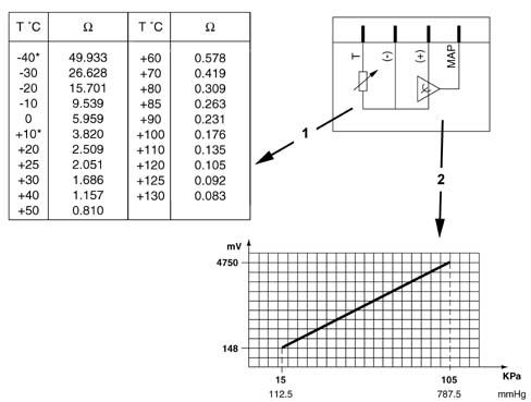
1, Air temperature sensor
2, Intake air pressure sensor
Electrical connections
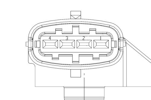
Pin 1, Earth
Pin 2, Air temperature sensor signal
Pin 3, 5V power supply
Pin 4, Air pressure signal in intake manifolds
IGNITION COILS
Composition
The coils are connected directly to the spark plugs and are the "PLUG TOP" type comprising a magnetic internal core made up of a silicon steel pack arranged along the axis of the coil and secondary and primary coils which contain the electrical windings, coaxial to the magnetic core.
The windings are housed in a pressed plastic container which has the low voltage connector and the fastening bush on the cylinder head and they are insulated through immersion in an epoxide resin which has excellent dielectric, mechanical and also thermal properties, as the coils are exposed to high temperatures. The proximity of the primary winding to the magnetic core reduces magnetic flux losses thereby ensuring optimum coupling at the secondary winding.
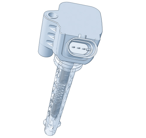
The head of the coil is connected to the spark plug by means of a silicone rubber cap which contains a spring that transfers the secondary winding high tension to the spark plug terminal.
The coils are directly controlled by the injection control unit in sequential timed mode.
The control unit earths the primary coil power supply circuit thereby creating a strong magnetic field on the primary coil. When the primary circuit is open a high voltage is produced at the secondary circuit through induction.
The high tension is discharged to the engine earth via the spark plug electrodes producing the spark that ignites the air/fuel mixture.
Electrical specifications:
Primary circuit resistance: 0.53 Ω ± 5% at 23°C
Secondary circuit resistance: 8100 Ω ± 5% at 23°C.
Rated current at primary winding: 7.3 A
Voltage at secondary winding: 27 kW
Electrical connections
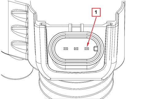
Pin 1, Connection to engine of engine secondary circuit
Pin 2, Primary circuit +12 V power supply
Pin 3, Control to earth from primary circuit control unit
Vehicle speed sensor
Specifications
The vehicle speed signal is produced by the ABS control unit and sent to the engine management control unit via the CAN.
TURBO PRESSURE SENSOR
Specifications
The turbo pressure sensor comprises a Wheatstone bridge serigraphed on a ceramic diaphragm and is used by the control unit for measuring the supercharging pressure downstream of the intercooler.
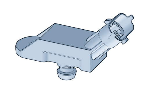
The sensor is fitted to the rigid intake pipe located before the motorised throttle valve.
The control unit uses the signal coming from the sensor to manage the supercharging pressure and to calculate the mass of air required for the subsequent fuel metering.
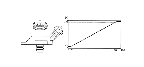
Pin 1, 5V power supply
Pin 2, Earth signal
Pin 3, Turbo pressure signal
SHUT-OFF SOLENOID
Specifications
It is a by-pass valve that includes a solenoid type on/off valve electrically controlled by the control unit.
The shut-off solenoid valve makes it possible to restrict excess pressure in the duct downstream of the compressor through the rapid closing of the throttle following a deceleration manoeuvre.
This excess pressure can create deceleration of the turbocharger impeller, causing a decline in performance and leading to strong vibrations and noise.
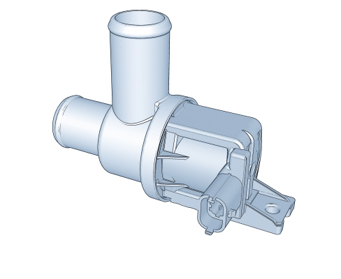
The shut-off solenoid valve is fitted on a dedicated bracket near the throttle body.
Operation
The solenoid valve comprises a casing enclosing a mechanical diaphragm valve (1) with a return spring (2) and an electromagnet (3) supplied by the injection control unit.
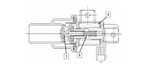
During overrun the injection control unit supplies the electromagnet (3) which attracts the mechanical valve (1) which opens a by-pass and discharges the excess intake pipe pressure upstream of the turbocharger.
Electrical properties
Supply voltage: 12V
Operating voltage: 8V - 16V
Current absorption: 1.4A (at 13V and 25 °C)
Electrical connections
Pin 1, +12V power supply
Pin 2, Control to earth from injection control unit
WASTE GATE SOLENOID VALVE
Specifications
The waste gate solenoid valve is used by the injection control unit to manage the turbo pressure through direct action via pneumatic connections with an actuator on the turbocharger.
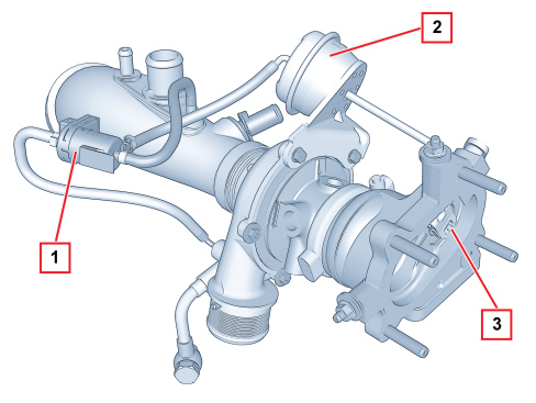
1. Solenoid valve
2. Actuator
3. Waste gate valve
The solenoid valve comprises a plastic casing that encloses a shutter and an electromagnet.
It is connected, via flexible pipes, to:
- turbocharger outlet (high pressure intake)
- waste gate valve actuator
- turbocharger air intake pipe (excess air pressure discharge).
The injection control unit measures the supercharging pressure in all engine operating ranges through the turbo pressure sensor. If this pressure exceeds the pre-set values, the control unit intervenes on the solenoid valve supplying the electromagnet which, attracting a shutter, releases the high pressure flow to the actuator thereby allowing the opening of the waste gate valve.
Once the regulation action is over, the electromagnet is no longer supplied and the high pressure is discharged upstream of the turbocharger.
Electrical properties
Electromagnet winding resistance: 30 Ohm +/- 10% at 20 °C
Electrical connections
Pin 1, Control to earth from control unit
Pin 2, +12V power supply
BRAKE PEDAL SWITCH
The dual stage brake pedal switch is used by the Engine Management Node to manage the strategies linked to driveability.
The brake pedal switch (1) is fitted on the pedal unit support as illustrated.
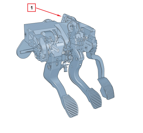
Specifications and operation
The brake pedal switch contains two switches, one normally open (N.A.) type and one normally closed (N.C.) type.
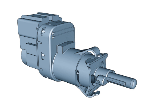

During operation, the (N.A.) switch closes, whilst the (N.C.) one opens, therefore the (N.C.) switch is designed to recognize the brake pedal in the rest position, whilst the (N.A.) switch is designed to recognize the brake pedal pressed.
The diagram below illustrates the internal electrical circuit with the brake pedal pressed and the operating diagram.
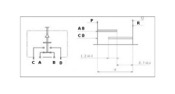
A. Power supply positive
B. Electrical consumer power supply
C - D. Redundant control switch
P. Brake pedal pressed status
R. Brake pedal released status
|
|
Both switches are closed in the halfway position, a situation used to check the consistency of the signal for the two switches. |
CLUTCH PEDAL SWITCH
The clutch pedal switch is used by the Engine Management Node to manage the strategies linked to driveability.
The clutch pedal switch (1) is fitted on the pedal unit support as illustrated.
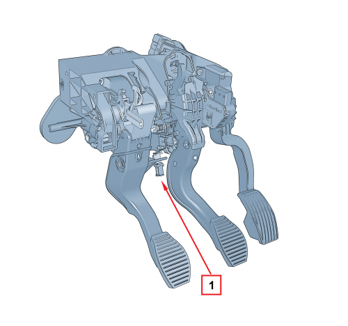
The switch comprises a casing that contains an (N.A.) switch which closes on a sliding track when the pedal is pressed.
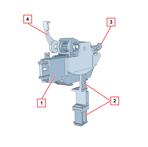
1. Connector
2. Outer lever with drive pin lock
3. Fastening tooth
4. Fastening lever
Electrical connections
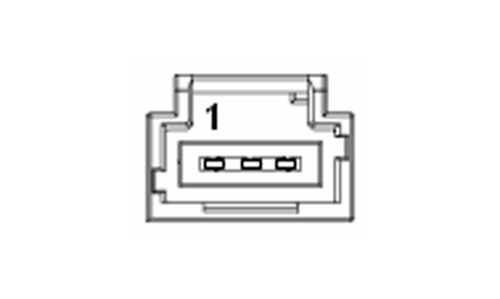
Pin 1. Frame earth connection
Pin 2. Not connected
Pin 3. Switch signal