GAS DISCHARGE - XENON HEADLAMPS
General information
Xenon technology is becoming increasingly more popular with respect to halogen lights because of the advantages they offer:
- higher light efficiency for decreasing electrical power draw;
- the high light flow emission makes it possible to reduce the dimensions of the light cluster (in particular the height) with greater freedom in the design of the front section;
- the life-span is in average double that of a halogen bulb.
- better visible for better obstacle vision (xenon lights provide three times more light than a halogen headlight)
- quicker reaction times: the road, the road side and the carriageway are better lit and the reaction times for avoiding obstacles are reduced;
- safer driving, deeper visibility and quicker perception of obstacles compensates the unpleasant feeling which accompanies driving at night and in poor weather thus increasing driving comfort.
The devices needed for operation are:
- xenon bulbs:
The light beam of a xenon bulb exceeds that of a halogen light in both depth and width allowing to identify obstacles better and faster. A xenon light is white and clear, not dissimilar from sun light (see light spectrum below).
The bulb contains xenon gas at a pressure of 3 bars. It is powered in high voltage generated by two photovoltaic arcs to produce light.
Xenon bulbs have a consumption of approximately 35 Watts, against the 55/60 Watts of traditional solutions. Reliability and duration are such to not require replacement for the entire life of the car.
The lighting power of xenon headlights is currently 3000 lumen, approximately double that of traditional halogen bulbs.
- elliptic lens:
The standard elliptic module is fitted inside the headlight and secured to the main beam spot reflector - control eletronics (ballast);
The main function of the ballast is to trigger the high voltage pulses to light up the bulb instantly and hold extra power for a few seconds in order to heat up the bulb electrodes, control the current and the voltage for maintaining the required light flow.
- dynamic beam height correction
The correct light beam during operation is guaranteed by an automatic dynamic correction system which adapts the beam to the load of the car and roughness of the road.
It mainly consists of two sensors fitted on the front/rear suspensions which control the headlight level.

|
The highway code requires the installation of a headlight washer/wiper system and an automatic beam correction system for xenon headlights. |
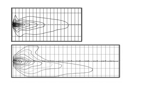
Light flow comparison (Isolux chart) comparing halogen source and gas discharge source
Headlight
The components needed for operating the system (lamp, ignitor, ballast, corrector motor) are integrated inside the light cluster along with the traditional components (side lights, direction indicators, dipped beam headlight).
The unit consists of:
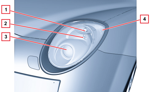
1 - Side/day light
2 - Main beam light (flasher)
3 - Dipped beam headlight - GAS DISCHARGE LAMP
4 - Direction indicator
The front light cluster is a headlight with a clear lens.
The body is made of polypropylene and is provided with housings for fastening to the body, upper centring to the mudguard, adjustable bushing to front end, message plate to front end, side plate to mudguard.
The housings and the fasteners for the assembly of the external lens, of the electric corrector and for the manual correction screws, the housing for the ballast, the housings for fastening the external mask and finally the housing for the bulb access caps are obtained in the body.
The reflector for the main lights, day lights and side lights is made of thermosetting material and integrates housings for the elliptic module (dipped beam/main beam) and for the partition which separates the main light zone from the day and side lights zone).
It is painted, metalized and protected.
The lens is made of polycarbonate and treated with scratchproof paint.

|
The switching between the dipped and main beam functions for xenon bulbs takes place by means of a suitably shaped metal screen that is lowered for main beam operation and raised for dipped operation. The additional spot main beam only comes on through the flasher control with the main beams switched off, whilst it is turned on together with the xenon bulb with the lights are switched from dipped to main beam. |
Bulbs present:
- Xenon D1S bulb for dipped-beam/main-beam headlights
- W21/5W all glass for the DRL/side lights - 12V-21/5W
- 12V-21W direction indicator module
- H7 halogen bulb for main beam headlights spot function 12V-55W.
Xenon bulb
The light source of a two-function xenon module is a D1S bulb mounted on an elliptical module powered at high voltage by an ignitor supplied by a ballast which converts the power values to those needed to trigger the arch in the range from approximately 20000 to 85 Volts (operations needed approximately 15 sec).
Light is generated by an arc sparked between two electrodes contained in the glass ampoule. The arc is maintained during the entire operation of the bulb.
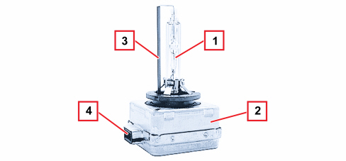
1 - Lamp
2 - Ignitor
3 - Ceramic insulation
4 - Connector
In detail, the operation of a xenon bulb consists of four phases:
- Ignition: During this stage the ballast produces a voltage capable of causing the engagement of a suitable device located in the ignitor. A step-up transformer circuit transfers the suitably amplified excess voltage to the bulb thereby causing a discharge between the electrodes.
- Take-over (arc maintenance): during this stage (lasting several seconds) the bulb receives the excess power supply necessary for producing the rapid evaporation of the metallic halides contained in the bulb in order to guarantee that the operating brightness is reached quickly. In these conditions the bulb produces a light flash that is twice the intensity of normal for a period of about 100 microseconds.
- Warm up for a period of about two minutes, the ballast regulates the light intensity determining the physical state of the bulb from its impedance properties (closed loop control).
- Steady state: the light beam is continuously controlled in a closed loop also in running conditions. The ignitor is arranged in the base of the lamp itself; the ballast is arranged in the control unit.
Front light cluster
Lamp rear view
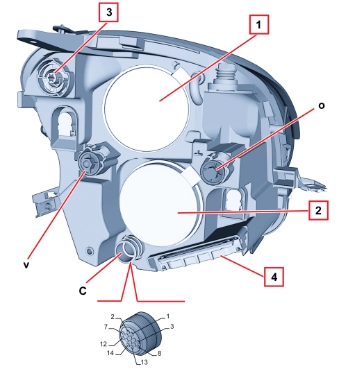
1 - Lid for day/side lights and additional main beam headlight
2 – Lid for D1S Xenon lamp
3 – Lid for direction indicator module
4 - Electronic control unit
o - Horizontal axis adjustment screw
v - Vertical axis adjustment screw
c – Headlight power 14-pin connector
Lamp connector
PIN OUT:
1- Xenon dipped headlamps control
2 - Direction indicators control
3 - Side lights control
4 - Main beam headlamps control
5 - Xenon bulb earth
6 - Ignition-operated power supply
6 - Ignition-operated power supply
7 - K diagnostic line
8 - Day light control
11 - Serial line between lamps and control unit
14 - Bulb Earth
Automatic headlamp alignment corrector
Xenon headlights must be equipped by law with a dynamic alignment corrector to prevent dazzling oncoming vehicles. The device works in the following conditions:
- static type, due to the distribution of the load;
- dynamic type, due to acceleration and deceleration.
The dynamic corrector also improves driving comfort because the illuminated area is stabilised and the driver’s eye does not need to constantly adapt to changes of lighting.
The device consists of:
- a stepper actuator for each headlamp.
- two load sensors, connected to the front and rear suspension, right side.
Correction
Light beam correction is made by means of the load sensor signal which, connected to the suspensions, provides an indication of vehicle load.
The control unit is activated at every Key on and resets the headlamps to the exact distance (calculated depending on the vehicle load) which consists of completely lowering and then positioning the reflector.
The load sensor signals are periodically acquired and a suitable average taken in order to readjust the position of the headlamp if necessary (e.g. fuel consumption whilst driving). This readjustment is not immediate. It is filtered in time to avoid undesired corrections (e.g. potholes, rough roads, etc.).
This correction is also made with the lights off, so that the moment the beam is switched on it is already correctly positioned.
Load sensors
The sensors are fastened to the vehicle bodyshell, whilst a suitable shaped lever follows the movement of the suspension.
The sensor receives a power supply from the headlamp control unit and provides a linear output signal proportional to the position of the suspension in relation to the bodyshell.
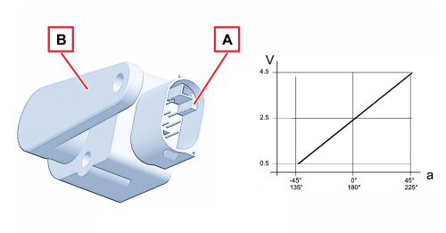
A - Part fastened to the bodyshell
B - Part fastened to the suspension linkage
a - Lever angle
V - Sensor output signal voltage
Adjustment actuator
A stepper actuator inside the light cluster carries out this adjustment. It consists of an electric stepper motor and a worm screw reduction unit which transforms the rotary motion of a hinged push rod into linear motion by means of a ball joint on the reflective surface.
Self-diagnosis
The electronics that manage the system have an auto diagnostic function that continuously checks operation.
The control unit carries out continuous self-diagnosis of system operation. In particular it detects and stores any faults.
The faults memorized in the control unit can be analyzed using the Examiner or other diagnostic equipment.
Recovery
The auto diagnostic management logic also has a recovery function: if errors are detected, the system no longer works properly and therefore the incorrect adjustment of the light beam could be dangerous and dazzle other vehicles.
The light beam is therefore positioned downwards in order not to dazzle anyone, but allows sufficient light to drive safely to a service centre.
The light beam is positioned downwards in the incorrect or lacking programming of the control unit.
Resetting
If the master control unit (in the left headlamp) is replaced, a self-learning procedure must be carried out, connecting to the diagnostic equipment, which makes it possible to automatically reset the system which should recognize the the position of the headlamp correctly aligned in position 0 from where the various adjustments can be set.