SPECIFICATIONS
The EPS (Electrical Power Steering) produced by DELPHI has a power assisted steering device which is designed to lighten the effort required from the driver on the steering wheel especially during steering manoeuvres at low speed without however making it too light in normal driving conditions.
The new EPS electronic module can receive a torque overlap request from an outside control unit and then apply the torque independently of what the driver has decided.
This steering torque dynamic control is the DST function (Dynamic Steering Torque) which improves driving safety and handling interacting with the VDC braking system electronic control unit.
For a more detailed description of the DST function
See descriptions 3350E VEHICLE DIRECTION CONTROL SYSTEM VDC/ESP
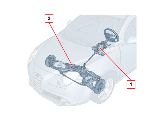

1. EPS power steering
2. Mechanical steering box
Electric power steering offers the following advantages compared with hydraulic power steering:
- The system has fewer components and therefore weighs less and is less complex.
- The installation and/or servicing times are reduced and simpler.
- The electric power steering system only absorbs energy from the engine when power assistance is requested, improving the performance of the vehicle and reducing consumption and emissions.
- A reduction in operating noise improves driving comfort.
- Reduction in pollution because the electrical energy used is clean.
- Variation in power assistance depending on the speed of the vehicle
- Steering return to the centre (active return)
- Steering return oscillation damping
- Power assistance that can be selected through "manettino" dials: Normal-Dynamic-All weather.
ACTIVATION STRATEGIES
The system operating strategy is illustrated in the diagram below.
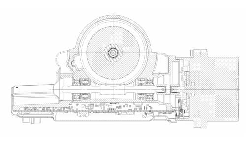
BASIC OPERATION
Depending on the driver's requirements (torque at the steering wheel) and the speed of the vehicle, the electric steering node management control unit (NGE) controls the electric servo motor that helps the steering column rotate.
The motor applies a torque to the actual steering column by means of a worm screw mechanism, thereby saving the driver steering effort.
Variable servo assistance depending on the speed of the vehicle
As the speed of the vehicle increases, the user increases the force applied to the steering wheel proportionally, because the resistant force at the wheels decreases as the vehicle speed increases.
As a result, making use of the vehicle speed signal, the NGE implements a lesser degree of steering assistance.
Active return
The return stage refers to the realignment function normally produced by the geometry of the vehicle's front section when the steering is released after steering.
This function is designed to make the realignment quicker causing the servo motor to intervene to help the normal geometric effect.
The active return correction varies depending on the speed of the vehicle:
- it is maximum at low speeds
- it is lowest at high speeds.
The servo motor carries out the active return of the steering wheel according to the steering angle in relation to the centre. The greater the steering angle, the greater the motor's effort to realign the wheels.
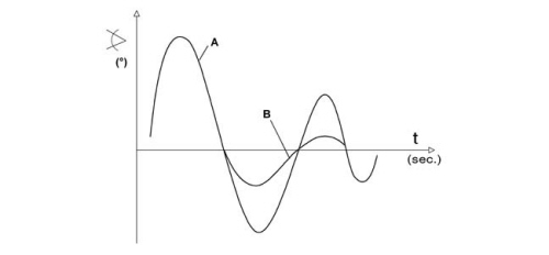
Steering return oscillation damping
After the steering wheel is released, following a steering manoeuvre, the vehicle chassis produces oscillations (A) which, if they persist for a while, can become tiresome.
The servo motor reduces the extent of the oscillations (B) during the return to the straight line driving route and intervenes more at high speeds.
Selectable power assisted steering
The system can choose between three driving modes using the vehicle dynamic control DNA selector.
“D” (Dynamic): this provides less assistance from the EPS control unit whilst the DST system strategies described for assembly 3350E are activated
See descriptions 3350E VEHICLE DIRECTION CONTROL SYSTEM VDC/ESP
“N” (Normal): this provides greater assistance from the EPS control unit whilst keeping all the DST system functions activated allowing easier driving when parking and at low/medium speeds.
“A” (All weather): this provides greater assistance from the EPS control unit but the LTF subfunction (Linerization Torque Feedback) for the DST system is deactivated.
Nge calibrations
The system manages 5 different driving calibrations. The NGE receives vehicle information (engine type and steering box type) from the Body Computer via the CAN and selects the correct calibrations from inside its memory.
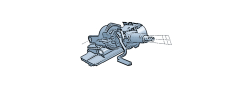
Axially and lengthwise adjustable column
COMPOSITION
The composition of the assembly is illustrated in the diagram below.
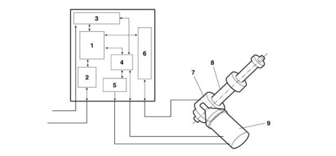
1. Microprocessor
2. CAN interface
3. Supply circuits
4. Engine phase operating circuit (EBMD)
5. Power electronics (FET)
6. Analogue signals interface
7. Position and torque sensor
8. Servo mechanism
9. Electric motor (with engine position sensor)
Geared motor
The geared motor comprises an aluminium casting secured to the vehicle chassis.
Located at the side of the geared motor casting, the servo motor supplies the interlocking gear with a torque ratio of 22:1 via a worm screw.
The geared motor gear, coaxial to the steering column and forming one piece, is made of steel, whilst the outer ring gear is made of moulded plastic. The worm screw and the gear have been designed so that the angles ensure the reversibility of the coupling.
The metal part of the gear is fitted on the output shaft which transmits the total steering forces (in other words the servo motor and driver torques).
The input and output shafts are joined to one another by a calibrated torsion beam which allows an angular movement of +8 degrees to -8 degrees (mechanical ends of travel prevent the torsion from being increased further).
If there is resistance at the wheels the input shaft twists the torsion beam therefore the input shaft and the output shaft are offset by an angle proportional to the torque applied to the steering wheel.
A torque sensor, fitted inside the geared motor, detects the change in angle between the input shaft and the output shaft and supplies an electric signal to the control unit that is proportional to the shift.
The casing for the geared motor also has the task of retaining the outer part of the torque and position sensor and lastly, the input shaft support cover is secured to the casing where the steering wheel is fitted and houses both the ignition switch and the steering column switch unit.
The axial position and angle of the steering wheel can be adjusted on the vehicle.

|
The geared motor casing must not, under any circumstances, be dismantled. It would also NOT be possible to reassemble this complex system like in the factory. |
Control unit
The control unit processes the input signals received from the sensors and operates the electric motor, providing a suitable current to achieve the desired assitance torque. It also manages the communication on the CAN and carries out the continuous auto diagnosis of the system to ensure correct operation. The communication on the CAN is managed using the diagnostic equipment.
The vehicle speed, alternator, Dynamic-Normal-All weather modes and tuning parameters are read from the CAN line.
The position and torque signals coming from the sensors represent the basic values with which the microprocessor processes the output data in terms of current supplied to the engine.
The steering power assistance control unit is fastened to the electric steering casing itself and interfaces with the wiring by means of two separate connectors: one 10 pin and one 2 pin.
CONTROL UNIT PIN OUT
The diagram below shows the control unit pin out.
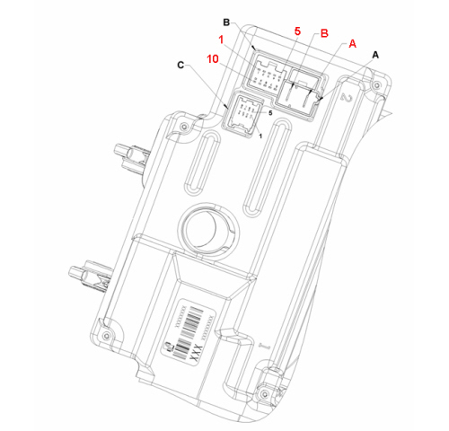
Connector A:
A - Battery +
B - Battery -
Connector B:
1 - Ignition
2 - CAN HI 2
3 - CAN LO 2
4 - N.C.
5 - N.C.
6 - N.C.
7 - CAN HI
8 - CAN LO
9 - N.C.
10 - N.C.
Connector C:
1 - Position 3 (VDC only)
2 - Position 1
3 - Sensor power supply
4 - T2
5 - N.C.
6 - Position 2
7 - Earth
Description of the signals
Normal/Dynamic driving mode selection signal
The Normal/Dynamic/All weather function has the task of varying the power assistance torque depending on the vehicle speed. It is possible to switch from Normal to Dynamic to All weather through a button.
The NGE system receives the Normal/Dynamic/All weather signal from the CAN and implements the requested strategy. The Body Computer control unit is prepared to receive the analogue signal that is altered when the button is released switching on the signal when the torque applied by the driver is more than 1 Nm.
During the ignition OFF/ON cycle, the Body Computer control unit maintains the status requested previously by the user.
Driving is always assisted (with the Dynamic configuration on, the power assistance is less).
CAN serial line
The control unit is capable of receiving/sending information on the CAN with this network interface operational from when the key is turned on until it is turned off.
Signals received / sent via the CAN
The following signals are received from the NGE via the CAN:
- Vehicle speed
- Failure light status
- Engine running signal (D+)
- Fault diagnosis
- Vehicle speed signal error
- Normal/Dynamic/All weather mode
- Type of tuning (calibration)
The following signals are sent by the NGE control unit via the CAN:
- System status (failure)
- Power assistance activated signal (EPS Active)
- Fault diagnosis
- Steering wheel absolute position (only for NGE version for applications with VDC)
OPERATION
The diagram showing the operation of the system is illustrated below.
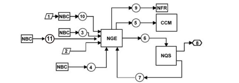
1. Dynamic driving selector
2. ignition key
3. alternator voltage
4. vehicle speed
5. steering load
6. failure warning light status sending
7. failure warning light status return
8. failure and/or Dynamic warning light lighting
9. steering angle position signal (only with VDC)
10. Dynamic / Normal signal from NBC
11. tuning type signal (calibration) from NBC
Operational behaviour
The operational behaviour of the system is illustrated in the table below.
|
INPUT |
OUTPUT |
|
Vehicle speed reading (4) (via CAN) |
Regulates the power steering depending on the speed of the vehicle and the recommended torque for the steering wheel. |
|
Alternator D+ reading (3) (via CAN) |
The control module is able to know from this reading whether the engine has been started. |
|
System error |
Failure warning light on via CAN |
|
Normal/Dynamic/All weather selection (included in the system) |
Depending on the request made by the driver using the button, the system activates the corresponding strategy (soft/hard). |
|
System electrical load (system reading) |
The system transmits this information to the engine control module via the CAN and the module, in turn, implements the appropriate strategy for regulating the engine idle speed. The control panel for the NGE node is capable of identifying the variations in the timing of the current absorbed by the node during operation. The control panel recognizes when the positive and negative thresholds are exceeded and transmits this information on the CAN. |
ELECTRIC MOTOR
Specifications
The electric motor is the three-phase self-switching synchronous type (without blades) with a permanent magnet rotor.
The distribution of the power and the control of the phases are regulated by the NGE management control unit.
Composition
The composition of the electric motor is illustrated in the diagram below.

The motor rotor is constructed using permanent magnetic material.
There is a disc with magnets (2) fitted to it, secured to the motor rotor (1), whilst there are three Hall effect semiconductors (3) on the fixed part of the crankshaft, output side. These notify the control unit of the angular position of the crankshaft through 360°. Therefore the position of the rotor (orientation) is measured by the position sensors built into the casing (Hall effect sensors), allowing the control unit to supply the suitable phases.

To reduce noise and pulsations at the steering column the motor is fitted with three insulators for the stator and one for the rotor.
Operation
The engine current uptake ranges from 1 A to 80 A; the maximum current uptake occurs when evasive measures are taken with high steering wheel rotation speeds.
The motor has been designed to provide the torque required, in other words it has been designed to help the user depending on the effort required on the steering wheel.
The wheels offer different resistance to the steering column depending on whether they are resting on ice or asphalt, for example.
As a result the motor provides the necessary torque.
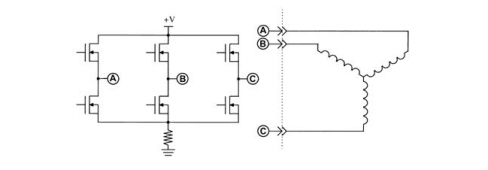
The control unit controls every single (three phase) winding. As the rotor has permanent magnets it tends to pursue and reach the centre of the magnetic field.
The control unit controls the position of the rotor through the signals sent by the Hall effect semiconductors.
The exact position of the rotor is used by the control unit to drive the current through the coils and maintain the engine torque
The activation of the individual coils takes place using the FET bridge illustrated above with a working frequency of 18 KHz and using the PWM (Pulse Width Modular) method for each individual coil.
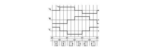
The diagram illustrates how, when the current is supplied to one winding, it is requested in another, whilst in the third winding no current flows through. On switching on, the current flows passing through the coils change.
The synchronized, self-switching motor always operates at the required torque determined by the force exerted by the user on the steering wheel and as the torque demand increases, the value of the current passing through the windings increases proportionally: this value will be around zero when no torque demand is placed on the engine.
The sensor
The sensor that measures torque and position is fitted on a single casing secured to the geared motor casting whilst the input and output shafts are free to rotate, driving the moving measurement parts.
As stated previously, the sensor has two functions: it measures the torque and the position of the output shaft.
When measuring the torque, it can be compared to a potentiometer where the resistive support is secured to the output shaft and the cursor is secured to the input shaft. The twisting moment on the torsion beam between the two shafts determines the value of the torque applied between the steering wheel and the steered wheels.
Through the signal from this potentiometer the control unit is capable of understanding the effort that the driver is exerting on the steering wheel, and the direction of the torque. Through the same principle (potentiometer), it measures the angular position of the output shaft in relation to the centre (wheels straight). Via the signal, the control unit is capable of understanding by how many degrees the steering wheel has moved in relation to the centre.
The sensor in question also has the function of a steering angle sensor and is designed to calculate the number of revolutions for the steering wheel and how many degrees per turn. The information supplied by the torque/position sensor is sent via the C CAN from the NGE node for the optimum management of the electronic stability control managed by the NFR.
|
|
It is prohibited to carry out tests on the sensors using any instruments: any fault diagnosis MUST be carried out using the electric steering control unit. |
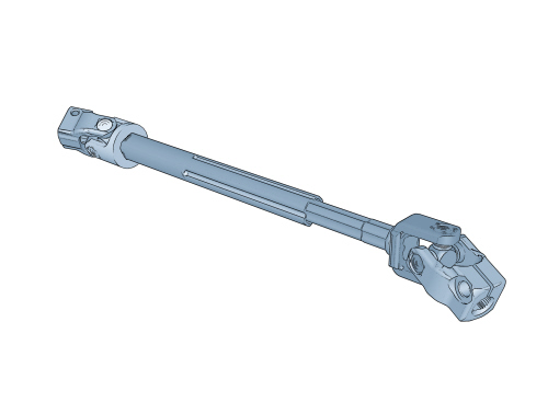
Lower Shaft
The connection between the steering column output shaft and the steering box pinion is made through a telescopic type intermediate shaft that is attached to the pinion by means of a splined fork with 26 teeth and a bolt.
Electric steering system protective fuses
The 70A power fuse protecting the direct supply system from the battery is located in the engine compartment on the battery. The ignition-controlled power supply (+15) is protected by a 7.5A fuse located on the Body Computer.