SPECIFICATIONS
The evaporation control system is designed to prevent the fuel vapours, consisting of the fractions of the lightest hydrocarbons that basically form in the tank, from being discharged into the atmosphere.
COMPOSITION
The system comprises a tank, a float valve, a two-way ventilation valve inside the fuel filler cap, an active charcoal filter, one-way safety valves and a carbon filter scavenging solenoid valve operated by the control unit.
OPERATION
The system works, in particular, at high outside temperatures when the temperature of the fuel increases and, as a result, the tendency to evaporation increases: in this situation there is an increase in the pressure inside the tank.
In particular, even with the tank full, the float valve remains open as it is located higher than the breather pipe and consequently it always allows the fuel vapours to reach the active charcoal filter thereby preventing fuel from escaping.
The fuel vapours reach the active charcoal filter when the pressure inside the tank causes the opening of the ventilation valve. This valve also allows an intake of air into the tank via the active charcoal filter if necessary after the fuel level has decreased.
With the engine running the control unit operates the active charcoal filter scavening valve which allows the intake of vapours by the engine and the consequent scavenging of the active charcoal filter.
If, as a result of this component malfunctioning, the pressure in the tank increases to dangerous levels, the safety valve located in the fuel filler cap allows the excess pressure to be discharged outwards. If necessary, this valve can open in the opposite direction to ventilate the tank and prevent the vacuum reaching levels that are too high.
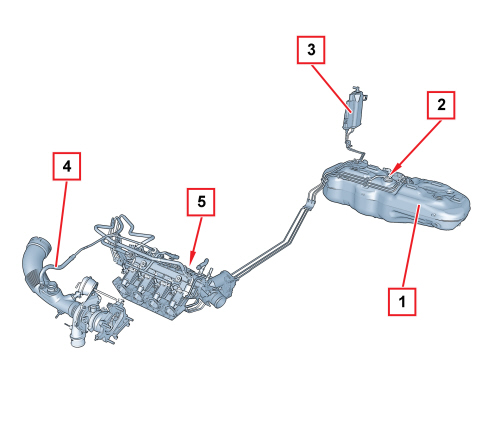
1. Fuel tank
2. Float valve
3. Activated charcoal filter
4. Fuel vapour supply pipe to turbocharger intake
5. Valve unit
EVAPORATION CONTROL SYSTEM COMPONENTS
Valve assembly
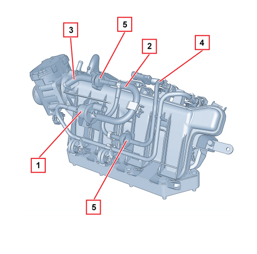
The fuel vapour solenoid valve (1) is located in the lower part of the air chamber and is connected to a pipe (2) which branches into two to reach a connector (3) downstream of the throttle on one side and a connector (4) upstream of the turbocharger on the other side.
This arrangement makes it possible to draw in the fuel vapours both when idling and during supercharging.
The recirculation pipes are fitted with one-way safety valves (5).
Float valve
This valve is used to perform the following functions:
- prevent the outflow of liquid fuel in the case of accidents where the vehicle overturns;
- allow the breathing of fuel vapours from the tank to the separator and to the active charcoal filter;
- allow tank ventilation if a vacuum builds up inside.
This valve consists of a casing (1) and float/needle valve (2).
Valve operation may be illustrated by the following scenarios that occur with different levels of fuel in the tank.
Full tank
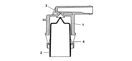
If the tank is full, the float (2) blocks the opening (3) to prevent liquid fuel from reaching the active charcoal filter.
Medium fuel level
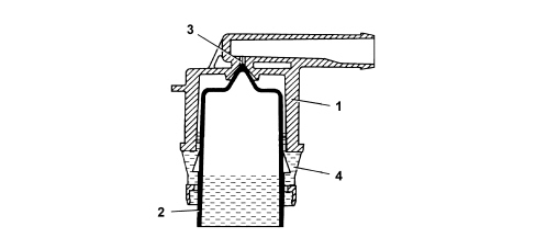
If the level of the fuel in the tank decreases, the float (2) descends and rests by means of the side tabs (4) on the slots in the valve casing (1) opening the port (3) that can be reached by the gases via the ring section between the float (2) and the valve body inner seat (1). This allows the fuel vapours to leave the tank and reach the active charcoal filter or, through the same circuit, to ventilate the tank when the internal pressure is lower than the outside pressure.
Seal in the case of roll over
If the vehicle rolls over, with the tank filled to any level, the float (2) acts under its own weight and the weight of the fuel on the port (3) to prevent a dangerous outflow of fuel to the active charcoal filters and the consequent risk of the vehicle catching fire.
Active charcoal filter (canister)
This is fitted to the right rear wheel arch and consists of an activated charcoal filter element that absorbs fuel vapours coming from the tank.
A one-way valve allows outside air (flushing air) to come in and flow over the charcoal granules to carry away the fuel vapours and convey them through the outlet to the intake manifold when fuel vapour solenoid is open.
Fuel vapour solenoid valve
The solenoid valve is the normally open type (if there is no supply the solenoid valve is closed) for the recirculation of fuel vapours.
It is used by the control unit for flushing the canister and is fitted in the lower part of the air chamber.

The solenoid valve comprises an outer plastic casing that encloses a shutter and an electromagnet.
There are two connectors at the ends for connection to the evaporation control system pipes.
The solenoid valve is controlled in PWM by the injection control unit depending on the mapped strategy.
When the electromagnet (1) is energized it attracts the shutter (2) which overcomes the load of the spring pack (3) to close the port (4) and prevent fuel vapours from passing through.
If there is no power supply the solenoid valve is closed.
Electrical properties
Supply voltage: 13.5V
Resistance at 20 °C: 26 Ohm
Operating frequency: up to 30 Hz
Current absorbed at 13.5V: 0.5 A
Electrical connections

Pin 1, +12V power supply
Pin 2, Control to earth from injection control unit
Safety and ventilation valve
Operation
This valve is built into the fuel filler cap and carries out the following functions, depending on the fuel pressure in the tank:
- discharging the excessive pressure that is created inside the tank outwards (safety function);
- allowing the flow of outside air into the tank when, as a result of the fuel consumption, an excessive vacuum is created in the tank (ventilation function).