SPECIFICATIONS
IHI RFH3 turbocharger with waste gate valve managed by the injection control unit via a turbo pressure solenoid valve.
Supercharging allows improved performance at low engine speeds, in order to make driving the vehicle more pleasant, without an excessive increase in fuel consumption.
Turbocharger
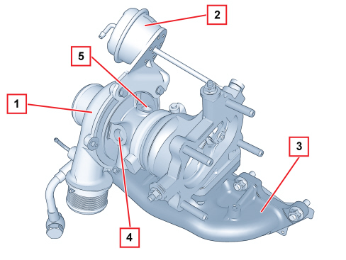
1. Turbocharger
2. Waste gate valve actuator
3. Exhaust manifold
4. Coolant inlet
5. Lubrication oil inlet
The turbocharger is connected directly to the oil filter (green filter) for the lubrication of the impeller and the cooling of the actual turbocharger.
The turbocharger is connected to the engine cooling circuit through dedicated pipes with natural type circulation.
The connection with the engine cooling circuit has the task of preventing a sudden change in temperature which takes place when the engine is switched off. This burst of heat can cause the oscillation of the lubrication oil on the turbine shaft with a consequent deposit of carbon.
Turbo pressure relief valve
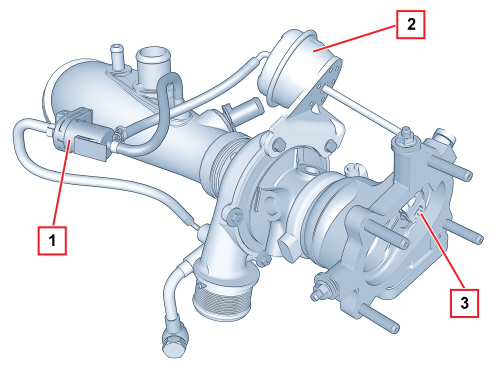
1. Solenoid valve
2. Actuator
3. Waste gate valve
The solenoid valve comprises a plastic casing that encloses a shutter and an electromagnet.
It is connected, via flexible pipes, to:
- turbocharger outlet (high pressure intake)
- waste gate valve actuator
- turbocharger air intake pipe (excess air pressure discharge).
The injection control unit measures the supercharging pressure in all engine operating ranges through the turbo pressure sensor. If this pressure exceeds the pre-set values, the control unit intervenes on the solenoid valve supplying the electromagnet which, attracting a shutter, releases the high pressure flow to the actuator thereby allowing the opening of the waste gate valve.
Once the regulation action is over, the electromagnet is no longer supplied and the high pressure is discharged upstream of the turbocharger.