

 Removing
(
Refitting
Removing
(
Refitting )
)
|
|
Removing
(
Refitting
)
|
|
|
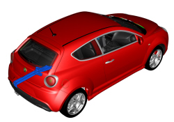
Op. 7210B56 R.R. BOOT LOAD COMPARTMENT FLOOR PLAN (PARTIAL REAR INTERVENTION) |
|
- Ensure that the components connected are not distorted by checking the body alignment measurements with suitable equipment (reference rigs, templates or gauges). - Straighten the body as necessary. |
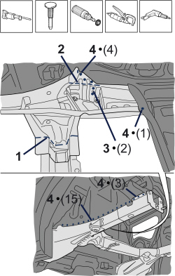  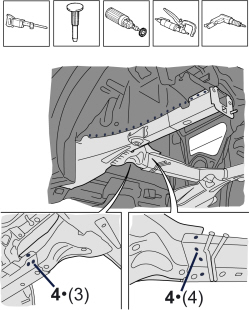 |
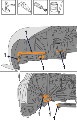
1. Use the jig saw, following the cutting line in the diagram. 2. Use the mallet and chisel to cut the part along the line shown in the figure. - Use a rotary brush to remove the paint and gain access to the spot welds. 3. Use the chisel and mallet to remove the spot welds shown in the diagram. 4. Use the chamfering machine to remove the spot welds shown in the diagram. - Use the drill to chamfer the spot welds that are not accessible to the chamfering machine. - Use a hammer and chisel to remove the previously chamfered spot welds. |
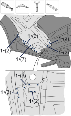  |
- Use a rotary brush to remove the paint and gain access to the spot welds. 1. Use the drill to chamfer the spot welds shown in the diagram. - Use a hammer and chisel to remove the previously chamfered spot welds. - Remove the part and the offcuts from the vehicle. |
  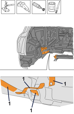 |
- Straighten the edges of the vehicle using a hammer and dolly block. - Remove the spot weld residues using a disc grinder. - Use a rotary brush to clean the previously treated areas. 1. Apply electro-weldable paint. |
  |
Refitting
(
Removing
)
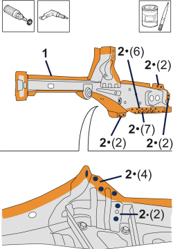
1. Remove the anti-corrosion treatment from the entire perimeter of the inside and outside of the replacement part using a rotary brush. 2. Drill out the part at the indicated points. - Apply electro-weldable paint to the edges involved. |
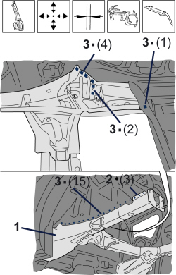  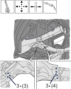 |
1. Position the replacement part correctly on the vehicle and secure it using self-locking clamps. - Check the alignment and the surrounding gaps. 2. Use a spot welder to weld the areas shown in the diagram. 3. Use a MIG welder to fill weld the openings made previously. |
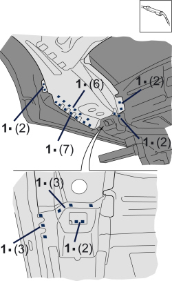  |
1. Use a MIG welder to fill weld the openings made previously. |
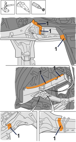  |
- Correct any distortions to the panel using a mallet and dolly block. 1. Smooth the weld spots with a grinding disk. - Use a rotary brush to clean the previously welded areas. |
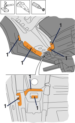  |
- Correct any distortions to the panel using a mallet and dolly block. 1. Smooth the weld spots with a grinding disk. - Use a rotary brush to clean the previously welded areas. |
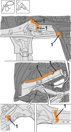  |
1. Apply anti-oxidant protection to the areas involved in the welding. - Seal the join lines between the replacement part and the vehicle. |
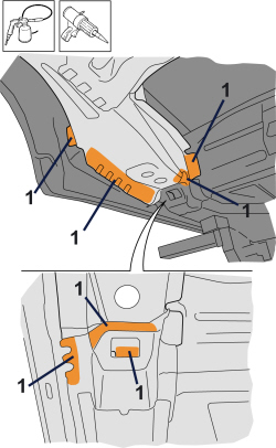  |
1. Apply anti-oxidant protection to the areas involved in the welding. - Seal the join lines between the replacement part and the vehicle. |
|
|
Op. 7210B56 R.R. BOOT LOAD COMPARTMENT FLOOR PLAN (PARTIAL REAR INTERVENTION) |
|
|
|