
 Removing
(
Refitting
Removing
(
Refitting )
)
- Drain the coolant.
Op. 0010T84 AIR CONDITIONING SYSTEM REFRIGERANT - DEHYDRATING AND REPRESSURIZING
|
|
Removing
(
Refitting
)
- Drain the coolant. Op. 0010T84 AIR CONDITIONING SYSTEM REFRIGERANT - DEHYDRATING AND REPRESSURIZING |
|
|
- Drain the engine coolant. |
|
|
|
|
|
|
|
|
Op. 5050A12 WINDSCREEN WASHER FLUID RESERVOIR FILLER PIPE (IN ENGINE COMPARTMENT) - R.R. |
|
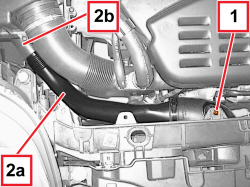  |
1. Unscrew the bolt. 2. Remove the cold air intake pipe (2a) releasing it from the connection (2b) for the air filter casing. |
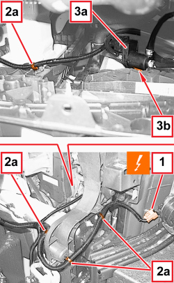  |
1. Working on the right side of the radiator unit, disconnect the electrical connection for the horns.
2. Disconnect the retainers (2a) for the electrical wiring from the front end assembly. 3. Disconnect the turbo pressure regulation solenoid valve (3a), releasing its retainer (3b). |
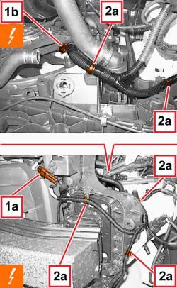  |
1. Working on the left side of the radiator unit, disconnect the electrical connections (1a, 1b).
2. Disconnect the retainers (2a) for the electrical wiring from the front end assembly. |
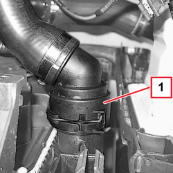  |
1. Working on the left side of the radiator unit, disconnect the rapid connector for the radiator coolant supply. |
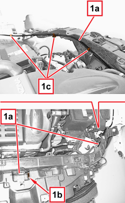  |
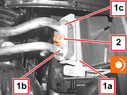
1. Extract the bonnet release cable (1a) from the passage (1b), then release it from the retainers (1c). |
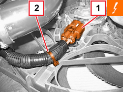  |
- Raise the vehicle. 1. Detach the electrical connection.
2. Disconnect the electrical wiring retainer. |
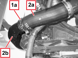  |
1. Working on the left side of the radiator unit, open the band (1a). 2. Disconnect the flexible pipe (2a) from the rigid pipe (2b) for the intercooler system. |
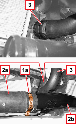  |
1. Working on the right side of the radiator unit, open the band (1a). 2. Disconnect the flexible pipe (2a) from the rigid pipe (2b) for the intercooler system. 3. Disconnect the rapid connector for the radiator coolant return. |
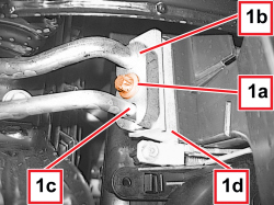  |
1. Undo the bolt (1a) and disconnect the pipe connectors (1b) and (1c) from the condenser (1d).
|
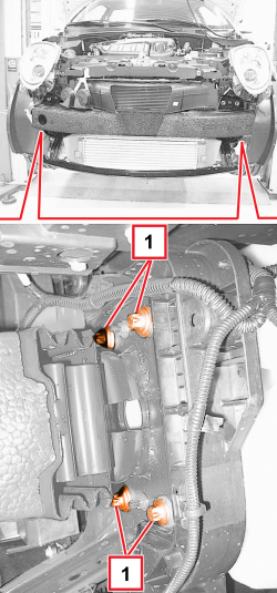  |
- Work on both sides of the vehicle. 1. Undo the bolts fixing the sacrificial crossmember to the body. |
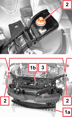  |
1. Position a board (1a) under the front end (1b) to support it during the removal stage. 2. Undo the upper front end bolts. 3. Remove the front end assembly with the help of a second mechanic. |
|
|
Refitting
(
Removing
)
PARTICOLARI DA SOSTITUIRE SISTEMATICAMENTE
|
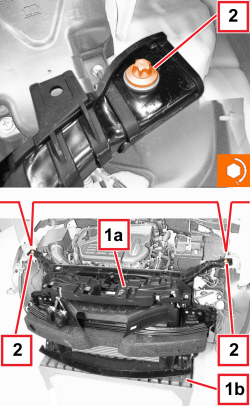  |
- Check that the front end assembly is not damaged. 1. Position the front end assembly (1a) with the help of the board (1b) and a second mechanic. 2. Screw in the front end upper bolts and tighten them to the specified torque.
|
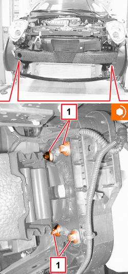  |
1. Screw in the bolts securing the sacrificial crossmember to the body and tighten them to the specified torque.
|
  |
1. Connect the pipe connectors (1b) and (1c) to the condenser (1a). 2. Tighten the bolt to the recommended torque.
|
|
|
- Working on the right side of the radiator unit, connect the rapid connector for the radiator coolant return. - Connect the flexible pipe to the rigid pipe for the intercooler system. - Fit the band. - Working on the left side of the radiator unit, connect the flexible pipe to the rigid pipe for the intercooler system. - Fit the band. - Connect the electrical wiring retainer. - Secure the fan electrical connection. - Lower the vehicle. - Fit the bonnet release cable to the crossmember retainers and passage. - Working on the left side of the radiator unit, connect the rapid connector for the radiator coolant supply. - Working on the left side of the radiator unit, connect the retainers for the electrical wiring to the front end assembly. - Connect the electrical connections for the Air Bag deceleration sensor and the fan resistor. - Working on the right side of the radiator unit, connect the turbo pressure regulation solenoid valve, engaging its retainer. - Connect the retainers for the electrical wiring to the front end assembly. - Connect the electrical connection for the horns. - Position the cold air intake pipe attaching it to the connection for the air filter casing, then tighten the bolt. Op. 5050A12 WINDSCREEN WASHER FLUID RESERVOIR FILLER PIPE (IN ENGINE COMPARTMENT) - R.R. |
|
|
|
|
|
|
|
|
|
- Refill the engine cooling circuit. |
|
- Repressurise the coolant. Op. 0010T84 AIR CONDITIONING SYSTEM REFRIGERANT - DEHYDRATING AND REPRESSURIZING |
|
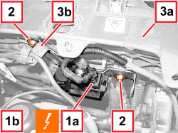  |
1. Disconnect the electrical connection (1a) for the turbocharger vane actuation solenoid valve (1b).
2. Unscrew the bolts. 3. Move the mounting (3b) with solenoid valve (1b) away from the front-end assembly (3a). |
|
|
1. Extract the bonnet release cable (1a) from the passage (1b), then release it from the retainers (1c). |
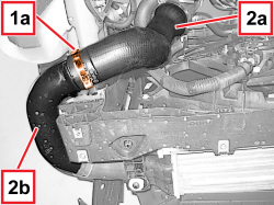  |
1. Working on the left side of the radiator unit, open the band (1a). 2. Disconnect the flexible pipe (2a) from the rigid pipe (2b) for the intercooler system. |
|
|
1. Position a board (1a) under the front end (1b) to support it during the removal stage. 2. Undo the upper front end bolts. 3. Remove the front end assembly with the help of a second mechanic. |
|
|
Refitting
(
Removing
)
PARTICOLARI DA SOSTITUIRE SISTEMATICAMENTE
|
|
|
1. Extract the bonnet release cable (1a) from the passage (1b), then release it from the retainers (1c). |
|
|
1. Undo the bolt (1a) and disconnect the pipe connectors (1b) and (1c) from the condenser (1d).
|
