
 Removing
(
Refitting
Removing
(
Refitting )
)
- Position the vehicle on a lift.
|
|
Removing
(
Refitting
)
- Position the vehicle on a lift. |
|
|
|
|
Op. 4410D17 REINFORCEMENT FOR FRONT SUSPENSION CROSSMEMBER - R.R. |
|
Op. 1076B72 INTERMEDIATE EXHAUST PIPE WITH HOSE SECTION - R+R |
|
|
Op. 5540C42 SENSOR FOR CORRECTING/ALIGNING GAS DISCHARGE LIGHT CLUSTERS ON FRONT SUSPENSION - R.R. |
|
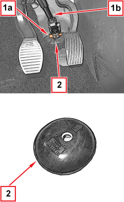  |
1. Undo the bolt (1a) fixing the steering column (1b) to the steering box pinion. 2. Remove the protection for the steering box pinion. |
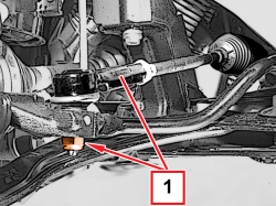  |
1. Undo the nut securing the steering rod to the left wheel strut. |
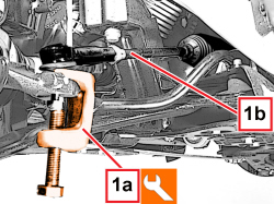  |
1. Using the tool (1a) disconnect the steering rod (1b) from the left steering knuckle.
|
|
|
- Carry out the same operations to disconnect the steering link from the steering knuckle, right side. |
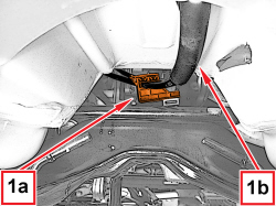  |
1. Open the clip (1a) and release the gear selector and engagement cables (1b) from the steering box. |
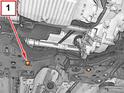  |
1. Undo the bolts fixing the steering box to the suspension crossmember. |
|
|
- Position a suitable hydraulic lift under the suspension crossmember. |
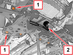  |
1. Undo the bolts securing the front suspension crossmember to the body. 2. Adjust the hydraulic lift to lower the suspension crossmember and remove the steering box. |
  |
Refitting
(
Removing
)
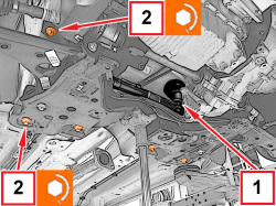
1. Place the steering box back in its housing. 2. Place the suspension crossmember in its housing and tighten the bolts to the recommended torque.
|
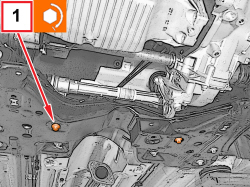  |
1. Tighten the bolts securing the steering box to the suspension crossmember to the specified torque.
|
|
|
- Attach the gear selection-engagement cables to the steering box and close the retaining clip. |
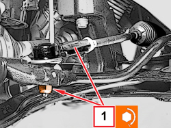  |
1. Connect the steering link to the left steering knuckle and tighten the new nut to the specified torque.
|
|
|
- Carry out the same operations to connect the steering link to the steering knuckle, right side. |
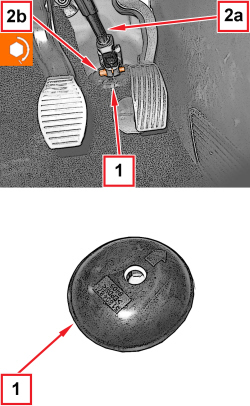  |
1. Place the steering box pinion protection in position checking that the printed arrow is facing the direction of travel. 2. Connect the steering column (2a) to the steering box pinion and tighten the bolt (2b) to the recommended torque.
|
|
|
Op. 5540C42 SENSOR FOR CORRECTING/ALIGNING GAS DISCHARGE LIGHT CLUSTERS ON FRONT SUSPENSION - R.R. |
|
|
Op. 1076B72 INTERMEDIATE EXHAUST PIPE WITH HOSE SECTION - R+R |
|
Op. 4410D17 REINFORCEMENT FOR FRONT SUSPENSION CROSSMEMBER - R.R. |
|
|
|
|
|
- Remove the vehicle from the lift. |
|
|
Refitting
(
Removing
)
1. Place the steering box back in its housing. 2. Place the suspension crossmember in its housing and tighten the bolts to the recommended torque.
|