145 - MiTo   1.4 16v TJet   REAR TWEETER SPEAKER CONNECTOR (ONE), LH OR RH - R.R.   5590G14   

Detail     Detail

Removing ( Refitting )

- Disconnect the negative battery terminal or, for cars equipped with the Start&Stop system, the "negative dummy pole".


Name


Connector


-


BATTERY


   See A001 BATTERY


-


TERMINAL BOX


   See A005 Contact board

   Op. 7040H80 REAR PARCEL SHELF - R.R.

- For the left side.

   Op. 7040G30 BOOT LIGHT BULB HOLDER - R.R.


Enlarge the image


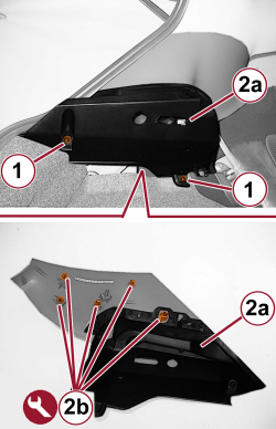
1. Undo the screws.

2. Move the rear side trim (2a) to one side, releasing the inner retainers (2b) using the appropriate tool.


Tool


Name


Function


Validity


1823015000


Knife


Retainer removal


- Lower the side trim without disconnecting it from the rear seat belt.


Enlarge the image


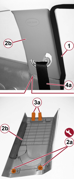
1. Prise up the door housing seal in the area of the central pillar cover.

2. Release the lower inner retainers (2a) for the cover (2b) using the appropriate tool.


Tool


Name


Function


Validity


1823015000


Knife


Retainer removal


3. Release the upper inner retainers (3a) and detach the cover (2b).

4. Lower the cover (2b) without releasing it from the seat belt (4a).


Enlarge the image


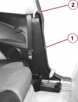
1. Release the door housing seal in the area of the side panel.

2. Undo the screw.


Enlarge the image


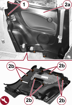
1. Undo the screws.

2. Move the upper part (2a) of the side panel, releasing the inner retainers (2b) using the appropriate tool.


Tool


Name


Function


Validity


1823015000


Knife


Retainer removal


Enlarge the image


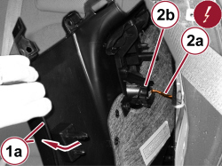
1. Move the front upper section (1a) of the side panel slightly.

2. Disconnect the electrical connection (2a) for the tweeter (2b).


Name


Connector


2a


REAR LEFT TWEETER SPEAKER


   See P047 LEFT REAR TWEETER SPEAKER


2a


REAR RIGHT TWEETER SPEAKER


   See P048 RIGHT REAR TWEETER SPEAKER


Enlarge the image


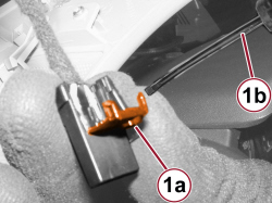
1. Raise the safety slit (1a) using a screwdriver (1b).


Enlarge the image


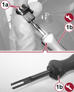
1. Extract the cables (1a) from the connector using the tool (1b).


Tool


Name


Function


Validity


2000018604


Extractor


Cable terminal extraction


- To replace the terminals proceed as follows.

These illustrations only refer to replacing an individual terminal for the connector block illustrated, but are valid for all families of connectors. If several terminals are being replaced, make offset junctions between them in order to restrict the size of the cable loom and thereby facilitate the subsequent refitting in the sheath.


Enlarge the image


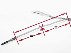
1. Release the cable for the terminal to be replaced sufficiently to work and cut at the midway point as illustrated in the figure.


Enlarge the image


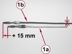
1. Measure the cable that has just been cut (1a), then cut the replacement cable (1b) 15 mm longer than the cable to be replaced.


Enlarge the image


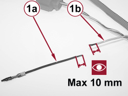
1. Strip the new replacement cable (1a) and the corresponding wiring cable (1b) for a maximum length of 10 mm.

To avoid cutting the strands and losing part of the cable conduction powers, it is advisable to expose the cables carefully.


Enlarge the image


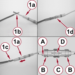
1. Fit the thermal restricting coupling tube (1a) on the wiring cable. Starting as illustrated in the figure (1b) twist the strands (1c), then move the coupling tube (1a) until the coupling is covered with the tin ring (1d) by the twisted strands (1c).

A. Thermal shrinking coupling tube

B. Adhesive ring

C. Tin ring

D. Twisted strands


Enlarge the image


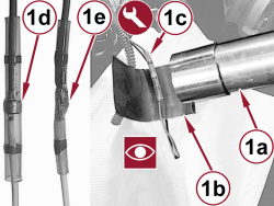
1. Using the drier (1a) fitted with the heat shield (1b) heat the thermal shrinking tube (1c) until the tin ring (1d) melts as illustrated in figure (1e).

Wait for the tin to cool down, then refit the wiring.


Tool


Name


Function


Validity


2.000.029.200


Sheet


Heat shield sheet


Take great care not to get the cables to be joined dirty as this will adversely affect the continuity of the electrical conduction. While heating the thermal shrinking tube, as a result of the high temperatures reached, the drier and the heat shield must not, under any circumstances, come into contact with clothes or other compartments.

The drier used in this procedure is commercially available.

Refitting ( Removing )

- Fit the terminals in the connector block checking that the retaining tabs are secured.

- Slightly pull every single cable checking that the terminals are secured correctly.

- Close again the safety slit.

- Connect the electrical connection for the tweeter.

- Position the side panel and attach the inner retainers.

- Tighten the upper screws securing the side panel.

- Raise the central pillar cover and position it engaging the retainers.

- Fit the door housing seal.

- Raise and position the rear side cover and engage the retainers.

- Do up the screws.

   Op. 7040G30 BOOT LIGHT BULB HOLDER - R.R.

   Op. 7040H80 REAR PARCEL SHELF - R.R.

- Connect the negative battery terminal or the "negative dummy pole".

- Check that the dismantled parts are working.