|
|
|
|
Test results |
|
|
Connectors |
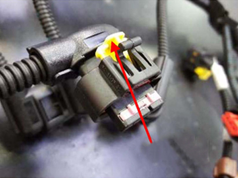
Check that all the connectors are correctly attached to the counterparts and that the CPA, if there are any, are closed (see fig. 1) (The figures can be viewed in the diagnosis in text format). |
Go to Step 2 |
There are loose connections or breaks in continuity |
Restore the correct connections or the correct continuity. Close the relative open CPA |
|
|
Earth ring terminals |
Check that the earth ring terminals are attached and the nuts tightened. Check for the yellow point indicating the torque is closed |
Go to Step 3 |
Earth rings not properly tightened |
Tighten the nuts with the dynamometer spanner, entering indication that the torque is closed |
|
|
Terminals |
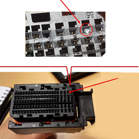
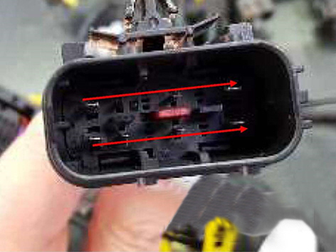
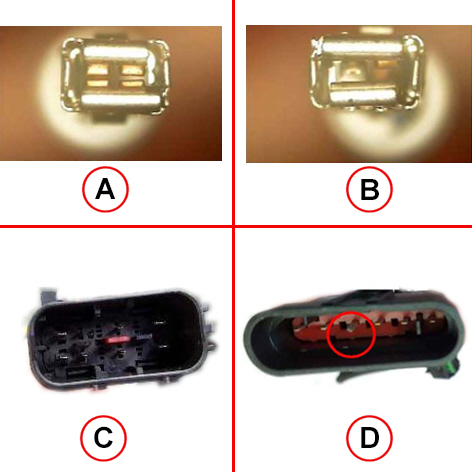
Check the continuity of the internal wiring to the tabs. Check that the male tabs are aligned (see fig. 2) (The figures can be viewed in the diagnosis in text format). Using the probe kit, check the continuity or presence of loose connections inside the female tabs |
Go to Step 4 |
1.Male tabs not aligned 2. Female tabs not correctly connected |
1. Push the wire into the cavity until the terminals realign. 2. Perform a traction test to be sure that they do not move (primary lock damaged). In case they move, replace the wire. In case they do not move, repeat the diagnosis to confirm that the fault has been eliminated |
|
|
Cable bundle wire |
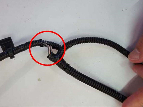
Check that there are no apparent cuts on the cable bundle, sheared wires or electrical jumper connections (see fig. 3) (The figures can be viewed in the diagnosis in text format). |
Go to Step 5 |
Wiring with signs of cuts on the cable bundle, sheared cables or electrical jumpers |
Replace the wiring |
|
|
Cable bundle wire |
Check the continuity and insulation of the wiring with a tester, being careful not to insert the points into the terminals. Also check the electrical continuity on the operation involved in the fault by slightly moving the part of the wire concerned. |
Go to Step 6 |
Interruption in the continuity or incorrect wiring insulation |
Restore the correct continuity or insulation of the wiring. Also check that the involved circuit terminals are correctly positioned and that there are no inversions on them. IN the case of terminal inversions, restore the correct positioning and repeat the diagnosis. Replace the wiring if the fault is reconfirmed |
|
|
Connectors |
Disconnect all the connectors involved in the fault on the entire connection line concerned and check for foreign bodies, grease or dust (see fig. 4) |
Go to Step 7 |
Presence of foreign bodies, grease or dust |
Remove the foreign bodies or clean the connection. Repeat the diagnosis to confirm the elimination of the fault |
|
|
Terminals and utilities connectors |
Check that the terminal wiring connections are not deformed (see fig. 5) (The figures can be viewed in the diagnosis in text format). Also check that the utilities connectors the terminals are connected to are not deformed |
Go to Step 8 |
Presence of deformed terminals |
Replace the wiring if there are deformations on the terminals. Replace the utilities that show deformities on the connectors |
|
|
E utilities |
Check the engine utilities connected to the wiring are working properly |
End of diagnosis |
At least one of the utilities is not working properly |
Replace the improperly functioning utilities |