
 Removing
(
Refitting
Removing
(
Refitting )
)
- Disconnect the negative battery terminal.
|
Name |
Connector | |
|
- |
BATTERY |
|
|
Removing
(
Refitting
)
- Disconnect the negative battery terminal.
|
|
|
Op. 7040G20 BULB HOLDER FOR COMPARTMENT LIGHTING IN DASHBOARD - R.R. |
|
|
|
Op. 7040L40 FRONT DOOR RUNNING BOARD (ONE), LEFT OR RIGHT - R.R. |
|
|
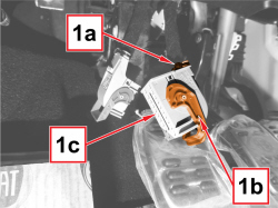  |
- Disconnect the rear electrical connections from the Body Computer. 1. Remove the retainer tie (1a) of the 20-pin Body Computer connector (1b) and extract the safety catch (1c). |
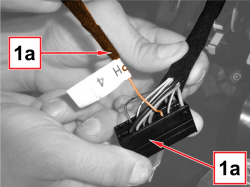  |
1. Disconnect the cable (1b) of the multimedia device electric wiring from pin 4 of the connector (1a). - Use the specific tool to extract the cable from the connector.
|
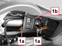  |
1. Recover the section of wiring (1a) from the on-board panel compartment (1b). |
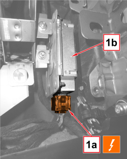  |
1. Disconnect the electrical connection (1a) for the voltage stabiliser (1b).
|
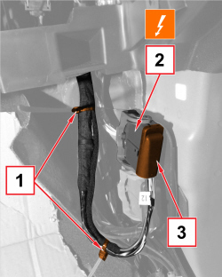  |
1. Cut the retainer ties off the electrical wiring for the multimedia device. 2. Disconnect the electric coupling.
3. Remove the cover and pull it out. |
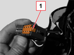  |
1. Remove the safety catch from the connector. |
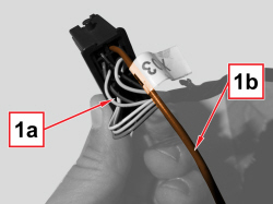  |
1. Disconnect the cable (1b) of the multimedia device electric wiring from pin 12 of the connector (1a). - Use the specific tool to extract the cable from the connector.
|
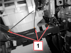  |
1. Cut the retainer ties off the electrical wiring for the multimedia device. |
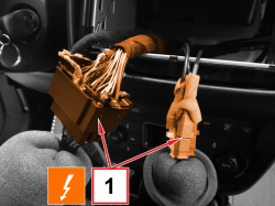  |
1. Disconnect the couplings for the dashboard wiring.
|
|
|
- Keep the electrical wiring for the multimedia device. |
|
|
Refitting
(
Removing
)
- Check that the multimedia device electric wiring is not damaged and that the individual conductors are correctly fastened to the connections. If necessary, carry out appropriate continuity tests. - Put the multimedia device electric wiring in position, restoring the layout. - Connect the electrical connections to the dashboard wiring. - Connect the electrical connection for the voltage stabilizer. - Connect the wiring to pin 12 of the front / dashboard coupling and replace the safety catch and the top cover. - Connect the electric coupling.
- Connect the cable to pin 4 of the 20-pin connector of the Body Computer, replace the safety catch and the cover and secure it with a new tie. - Secure the multimedia device electric wiring with new retainer ties. |
|
|
|
Op. 7040L40 FRONT DOOR RUNNING BOARD (ONE), LEFT OR RIGHT - R.R. |
|
|
|
Op. 7040G20 BULB HOLDER FOR COMPARTMENT LIGHTING IN DASHBOARD - R.R. |
|
|
|
- Connect the negative battery wire terminal.
|