
 Removing
(
Refitting
Removing
(
Refitting )
)
- Place the vehicle on a lift.
|
|
Removing
(
Refitting
)
- Place the vehicle on a lift. |
|
|
|
|
|
|
|
|
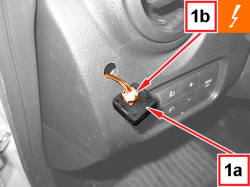  |
1. Release the LPG/petrol selection switch (1a) and disconnect the electrical connection (1b).
|
|
|
- Release the wiring through the fuse hole on the instrument panel. |
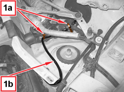  |
1. Mark the position of the retaining bands (1a) for the wiring (1b). - Keep the disconnected wiring. |
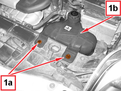  |
1. Undo the screws (1a) and move the engine coolant reservoir (1b) to one side. |
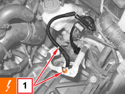  |
1. Undo the nut and disconnect the wiring from the battery positive terminal. |
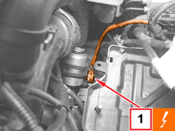  |
1. Disconnect the electrical connection for the LPG cut out solenoid valve coil.
|
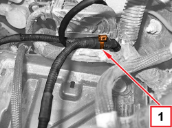  |
1. Mark the position of the wiring retaining band shown and remove it. |
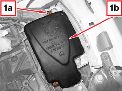  |
1. Undo the screws (1a) and remove the cover from the fuse and relay switch box (1b). |
|
|
- Act on the retaining clips and release the fuse and relay box from the mounting housing. |
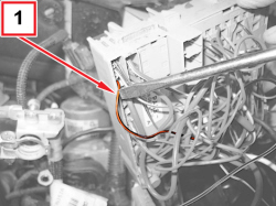  |
1. Disconnect the ORANGE/BLACK wire (pin 12) from the RED/WHITE cable of the LPG wiring. |
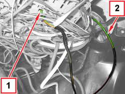  |
1. Disconnect the GREEN/ORANGE terminal (pin 49) from the BLACK wire of the LPG wiring. 2. Disconnect the GREEN/ORANGE terminal from the BLACK/RED wire of the LPG wiring. |
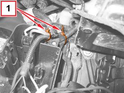  |
1. Mark the position of the wiring retaining bands shown and remove them. |
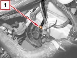  |
1. Undo the nut and release the wiring. |
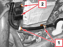  |
1. Mark the position of the wiring retaining bands shown and remove them. 2. Undo the nut and release the LPG supply relay switch wiring. |
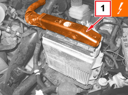  |
1. Disconnect the electrical connection for the LPG control unit.
|
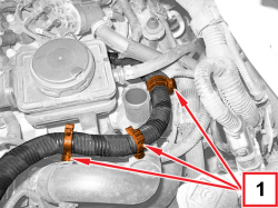  |
1. Open the wiring retaining clips shown in the figure. |
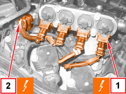  |
1. Disconnect the electrical connections for the LPG injectors.
2. Disconnect the electrical connection for the LPG temperature and pressure sensor.
|
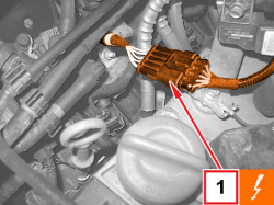  |
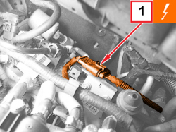
1. Disconnect the petrol injectors wiring front coupling.
|
  |
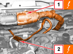
1. Disconnect the petrol injectors wiring rear coupling.
|
  |
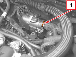
1. Disconnect the electrical connection for the petrol injection control unit.
2. Disconnect the multivalve wiring coupling.
|
  |
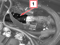
1. Mark the position of the wiring retaining band shown and remove it. |
  |
1. Open the side clips to release and remove the upper guard for the connector shown in the figure. |
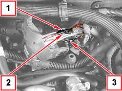  |
1. Disconnect the BLUE/RED wire (pin 43) from the ORANGE cable of the LPG wiring. 2. Disconnect the ORANGE/GREEN wire (pin 31) from the BROWN cable of the LPG wiring. 3. Disconnect the WHITE/RED wire (pin 25) from the YELLOW/RED wire of the LPG wiring. |
|
|
- Remove the cable loom for the LPG system releasing it from the engine. |
|
|
Refitting
(
Removing
)
- The branch of the LPG supply system wiring includes three wires that must be connected to the connector 60 of the petrol injection control unit as below described. ORANGE wire connection - Connect with a single winding the BLUE/RED wire (pin 43) of the petrol injection control unit connector to the end of the ORANGE wire for the LPG wiring. - Weld the wire braid previously connected and then wind up with a suitable insulating tape the welded area. BROWN wire connection - Connect with a single winding the ORANGE/GREEN wire (pin 31) of the petrol injection control unit connector to the end of the BROWN wire for the LPG wiring. - Weld the wire braid previously connected and then wind up with a suitable insulating tape the welded area. YELLOW/RED connection - Connect with a single winding the WHITE/RED wire (pin 25) of the petrol injection control unit connector to the end of the YELLOW/RED wire for the LPG wiring. - Weld the wire braid previously connected and then wind up with a suitable insulating tape the welded area. |
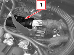  |
1. Place the wiring guard for the connector in its housing, as shown, and engage the side retaining clips. |
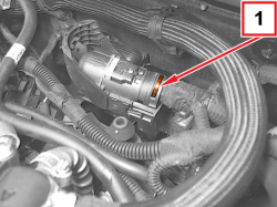  |
1. Fit a wiring retaining band as shown. |
|
|
- Connect the electrical connection for the petrol injection control unit. - Connect the petrol injector wiring junctions. - Connect the electrical connections for the LPG injectors. - Connect the electrical connection for the LPG temperature and pressure sensor. |
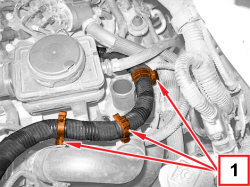  |
1. Engage the wiring with the retaining clips shown. |
|
|
- Secure the electrical connection for the LPG control unit. |
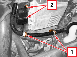  |
1. Engage the wiring with the retaining bands, positioned as shown. 2. Fit the LPG supply relay switch in position and tighten the nut. |
|
|
- Place the LPG wiring earth lead in position and secure it using the nut. |
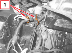  |
1. Engage the wiring with the retaining bands, positioned as shown. |
|
|
- The branch of the LPG supply wiring, fuse and relay switch box side, includes the BLACK, RED/BLACK and RED/WHITE wires to be connected as below described. BLACK wire connection - Insert a 30-mm long heat-shrinking sheath in the BLACK wire. - Connect with a single winding the GREEN/ORANGE wire (pin 49) of the fuse and relay box to the end of the BLACK wire for the LPG wiring. - Weld the braid of the previously connected wires, leaving the part closer to the sheath free, to allow subsequent bending. - Bend the braid of the wires previously welded, positioning it parallel to one of the wires. - Apply the heat-shrinking sheath in the wire connecting area. RED/BLACK wire connection - Insert a 30-mm long heat-shrinking sheath in the RED/BLACK wire. - Connect with a single winding the other end of the GREEN/ORANGE wire of the fuse and relay box to the end of the BLACK/RED wire for the LPG wiring. - Weld the braid of the previously connected wires, leaving the part closer to the sheath free, to allow subsequent bending. - Bend the braid of the wires previously welded, positioning it parallel to one of the wires. - Apply the heat-shrinking sheath in the wire connecting area. RED/WHITE wire connection - Connect with a single winding the ORANGE/BLACK wire (pin 12) of the fuse and relay box to the end of the RED/WHITE wire for the LPG wiring. - Weld the braid of the previously connected wires, leaving the part closer to the sheath free, to allow subsequent bending. - Weld the wire braid previously connected and then wind up with a suitable insulating tape the welded area. |
|
|
- Fit the fuse and relay switch box in position, engaging the retaining clips. - Fit the fuse and relay box gear selector spring cover in its housing and tighten the screws. |
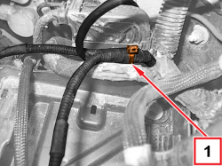  |
1. Engage the wiring with the retaining band, positioned as shown. |
|
|
- Connect the electrical connection for the LPG cut out solenoid valve coil. - Connect the wiring to the battery positive terminal and tighten the relevant nut. - Fit the engine cooling supply reservoir in place and secure it using the screws. |
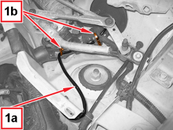  |
1. Engage the branch for the wiring for the LPG/petrol selection switch (1a) and engage the retaining bands (1b). |
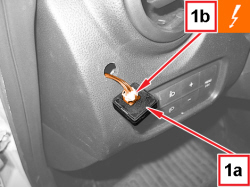  |
1. Connect the LPG/petrol selection switch (1a) to the electrical connection (1b).
|
|
|
- Place the LPG/petrol switch in its housing pressing on its edges, so that it sticks to the dashboard trim.
|
|
|
|
|
|
|
|
|
|
|
- Remove the vehicle from the lift. |
