|
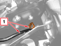
- Return the vehicle to the workshop (in petrol operation mode) and place it on a lift.
|
|
|
- Raise the vehicle.
|

|
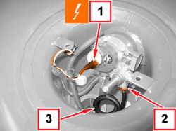
1. Disconnect the electrical connection for the LPG level gauge.
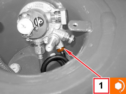
2. Unscrew the connector for supply pipe from tank to LPG pressure regulator.
3. Bend the coils of the supply pipe from tank to LPG pressure regulator upwards.
|
|
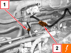
1. Open the multivalve wiring retaining clip.
2. Disconnect the multivalve wiring coupling.
|
|
|
- Remove the bands and separate the multivalve wiring from the supply pipe from tank to LPG pressure regulator.
|
|
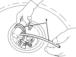
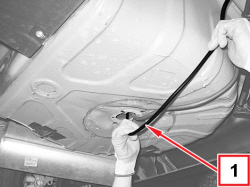
1. Insert the end of the section previously extended over the fuel vapour pipes into the petrol filler and, passing through the LPG tank pipe bushing, introduce about half a metre.
- Model the pipe with a semicircular shape as shown.
|
|
|
- Suitably secure the pipe bundle still to be extended next to the petrol tank.
|
|
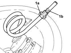
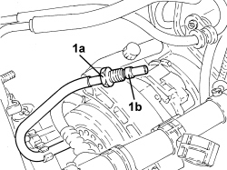
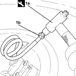
1. Fit the end of the supply pipe from tank to LPG pressure regulator in the tool (1a), until the end of travel, then tighten the connector (1b) to lock the nose.
|
2000033700 |
Connector |
Nose locking for LPG pipe connector |
1.4 16v TJet 120 HP |

|
For a correct locking of the nose, approach it manually and then, with a suitable spanner, make a further 2-3 complete turns of the connector on the tool.
|
|
|
|
|
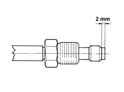
Check that the nose is 2 mm from the terminal of the supply pipe from tank to LPG pressure regulator.
|
|
|
|
- Fit the opposite end of the multivalve wiring in the spare wheel compartment, passing through the pipe bushing.
|
|
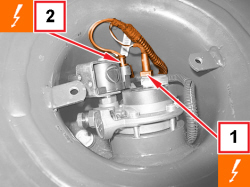
1. Connect the electrical connection for the LPG level gauge.
2. Connect the electrical connection for the LPG intake solenoid valve coil.
|
|
|
- Raise the car and place the supply pipe from tank to LPG pressure regulator in position, following a path perpendicular to the driving direction, then raise the pipe shaping it.
- Pass the multivalve wiring parallel to the supply pipe from tank to LPG pressure regulator extended previously.
|
|
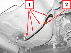
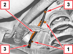
1. Engage the LPG pipes and the multivalve wiring with the bands positioned as shown.
2. Fit the rubber cylinder in the position shown.
|
|
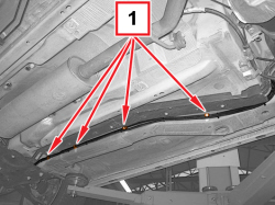
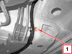
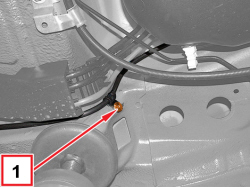
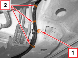
1. By the rivets, cut the rubber bands in the positions shown.
2. Fit the rubber coil making it touch the two rubber bands.
3. Engage the LPG pipe and the multivalve wiring with the bands positioned as shown.
|
|
|
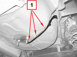
- Next to the petrol tank passage, protect the delivery pipe from tank to LPG pressure regulator with three rubber cylinders, secured with bands.
|
|
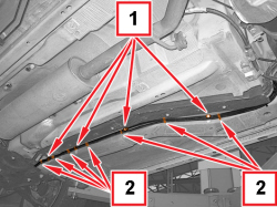
1. By a rivet, cut the rubber band in the position shown.
2. Engage the LPG pipe and the multivalve wiring with the bands positioned as shown.
|
|
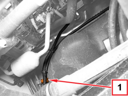
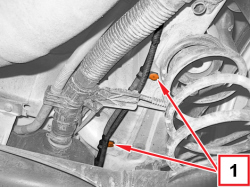
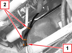
1. By the rivets, cut the rubber bands in the positions shown.
2. Engage the LPG pipe and the multivalve wiring with the bands positioned as shown.
|
|
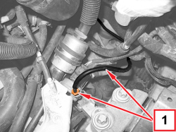
1. Engage the supply pipe from tank to LPG pressure regulator with the retaining clip shown.
2. Engage the LPG pipe and the multivalve wiring with the bands positioned as shown.
|
|
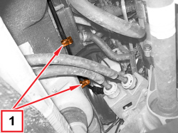
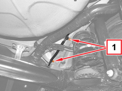
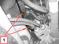
1. Engage the supply pipe from tank to LPG pressure regulator with the retaining clips as shown.
- Next to the servo brake, protect the supply pipe from tank to LPG pressure regulator with three rubber cylinders, secured with bands.
|
|
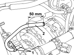
1. Press to engage the supply pipe from tank to LPG pressure regulator with the retaining clip, as shown.
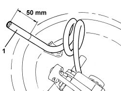
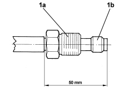
2. Cut and remove the sheath from the end of the supply pipe from tank to LPG pressure regulator, by 50 mm.
|
|
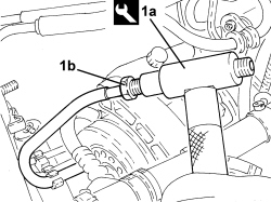
1. Fit the end of the supply pipe from tank to LPG pressure regulator in the tool (1a), until the end of travel, then tighten the connector (1b) to lock the nose.
|
2000033700 |
Connector |
Nose locking for LPG pipe connector |
1.4 16v TJet 120 HP |
|
|
For a correct locking of the nose, approach it manually and then, with a suitable spanner, make a further 2-3 complete turns of the connector on the tool.
|
|
|
|
|
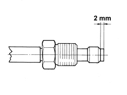
Check that the nose is 2 mm from the terminal of the supply pipe from tank to LPG pressure regulator.
|
|
|
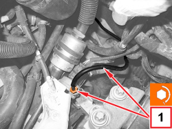
1. Connect the supply pipe from the tank to the LPG pressure regulator, regulator side and tighten the connector to the prescribed torque.
|
|
Next to the connector, the supply pipe from tank to LPG pressure regulator must be straight by at least 10 mm.
|
|
|
|
- Connect the multivalve wiring junction and engage the retaining clip.
|
|
|
- Remove the vehicle from the lift.
|
APPLIES TO VERSIONS WITH: Euro 5
APPLIES TO VERSIONS WITH: Euro 5
|
|
- Return the vehicle to the workshop (in petrol operation mode) and place it on a lift.
|
|
APPLIES TO VERSIONS WITH: Euro 5
APPLIES TO VERSIONS WITH: Euro 5
APPLIES TO VERSIONS WITH: Euro 5
APPLIES TO VERSIONS WITH: Euro 5
APPLIES TO VERSIONS WITH: Euro 5
APPLIES TO VERSIONS WITH: Euro 5
APPLIES TO VERSIONS WITH: Euro 5
APPLIES TO VERSIONS WITH: Euro 5
APPLIES TO VERSIONS WITH: Euro 5
APPLIES TO VERSIONS WITH: Euro 5
|
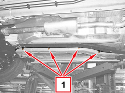
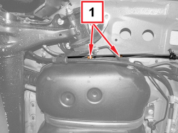
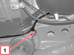
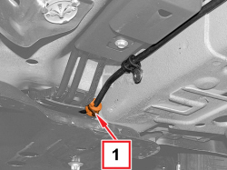
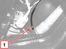
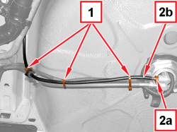
1. Mark the position and cut the bands indicated in the figure.
2. Unscrew the connector (2a) and remove the supply pipe from tank to LPG pressure regulator (2b).
|
|
APPLIES TO VERSIONS WITH: Euro 5
|
|
 Refitting
(
Removing Refitting
(
Removing )
)
- Obtain a new supply pipe from tank to LPG pressure regulator (diameter 6 mm) the same length as the pipe which was removed. - Proceed as described below for both ends. |
|
APPLIES TO VERSIONS WITH: Euro 5
APPLIES TO VERSIONS WITH: Euro 5
|
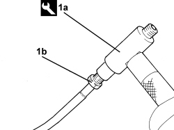
1. Fit the end of the supply pipe from tank to LPG pressure regulator in the tool (1a), until the end of travel, then tighten the connector (1b) to lock the nose.
|
2000033700 |
Connector |
Nose locking for LPG pipe connector |
1.4 16v TJet 120 HP |
|
|
For a correct locking of the nose, approach it manually and then, with a suitable spanner, make a further 2-3 complete turns of the connector on the tool.
|
|
|
APPLIES TO VERSIONS WITH: Euro 5
|
|
|
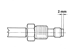
Check that the nose is 2 mm from the terminal of the supply pipe from tank to LPG pressure regulator.
|
|
|
APPLIES TO VERSIONS WITH: Euro 5
|
|
Manually shape the new supply pipe from tank to LPG pressure regulator, using the same references as for the pipe which was removed.
|
|
Pay attention not to create obstructions in the pipe.
|
- Place the supply pipe from tank to LPG pressure regulator back in its housing.
|
|
APPLIES TO VERSIONS WITH: Euro 5
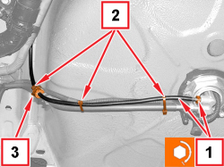
|
1. Apply a drop of lubricating oil to the thread of the connector for the supply pipe from tank to LPG pressure regulator, tank side, and tighten it to the prescribed torque.
2. Engage the LPG pipes and the multifunction solenoid valve wiring with the bands positioned as shown in the figure.
3. Protect the pipe with a rubber cylinder fixed with a band in the position indicated in the figure.
|
|
APPLIES TO VERSIONS WITH: Euro 5
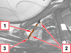
|
1. Fit the protective rubber coil in the point indicated in the figure.
2. By the rivets, cut the rubber bands in the positions shown.
3. Protect the pipe with a rubber cylinder fixed with a band in the point indicated in the figure.
|
|
APPLIES TO VERSIONS WITH: Euro 5
APPLIES TO VERSIONS WITH: Euro 5
APPLIES TO VERSIONS WITH: Euro 5
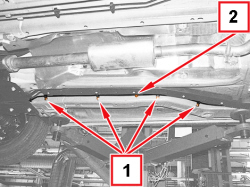
|
1. By the rivets, cut the rubber bands in the positions shown.
2. Protect the pipe with a rubber cylinder fixed with a band in the point indicated in the figure.
|
|
APPLIES TO VERSIONS WITH: Euro 5
APPLIES TO VERSIONS WITH: Euro 5
APPLIES TO VERSIONS WITH: Euro 5
|
1. Engage the supply pipe from tank to LPG pressure regulator with the retaining clips as shown.
- Next to the servo brake, protect the supply pipe from tank to LPG pressure regulator with three rubber cylinders, secured with bands.
|
|
APPLIES TO VERSIONS WITH: Euro 5
APPLIES TO VERSIONS WITH: Euro 5
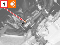
|
1. Connect the supply pipe from the tank to the LPG pressure regulator, regulator side and tighten the connector to the prescribed torque.
|
|
Next to the connector, the supply pipe from tank to LPG pressure regulator must be straight by at least 10 mm.
|
|
|
APPLIES TO VERSIONS WITH: Euro 5
APPLIES TO VERSIONS WITH: Euro 5
|
|
- Remove the vehicle from the lift.
|
|
APPLIES TO VERSIONS WITH: Euro 5
APPLIES TO VERSIONS WITH: Euro 6
APPLIES TO VERSIONS WITH: Euro 6
|
|
- Return the vehicle to the workshop (in petrol operation mode) and place it on a lift.
|
|
APPLIES TO VERSIONS WITH: Euro 6
APPLIES TO VERSIONS WITH: Euro 6
APPLIES TO VERSIONS WITH: Euro 6
APPLIES TO VERSIONS WITH: Euro 6
APPLIES TO VERSIONS WITH: Euro 6
APPLIES TO VERSIONS WITH: Euro 6
APPLIES TO VERSIONS WITH: Euro 6
APPLIES TO VERSIONS WITH: Euro 6
APPLIES TO VERSIONS WITH: Euro 6
APPLIES TO VERSIONS WITH: Euro 6
|
1. Mark the position and cut the bands indicated in the figure.
2. Unscrew the connector (2a) and remove the supply pipe from tank to LPG pressure regulator (2b).
|
|
APPLIES TO VERSIONS WITH: Euro 6
|
|
Refitting
(
Removing
)
- Obtain a new supply pipe from tank to LPG pressure regulator (diameter 6 mm) the same length as the pipe which was removed. - Proceed as described below for both ends. |
|
APPLIES TO VERSIONS WITH: Euro 6
APPLIES TO VERSIONS WITH: Euro 6
|
1. Fit the end of the supply pipe from tank to LPG pressure regulator in the tool (1a), until the end of travel, then tighten the connector (1b) to lock the nose.
|
2000033700 |
Connector |
Nose locking for LPG pipe connector |
1.4 16v TJet 120 HP |
|
|
For a correct locking of the nose, approach it manually and then, with a suitable spanner, make a further 2-3 complete turns of the connector on the tool.
|
|
|
APPLIES TO VERSIONS WITH: Euro 6
|
|
|
Check that the nose is at 2 mm from the terminal of the supply pipe from tank to LPG pressure regulator.
|
|
|
APPLIES TO VERSIONS WITH: Euro 6
|
|
Manually shape the new supply pipe from tank to LPG pressure regulator, using the same references as for the pipe which was removed.
|
|
Pay attention not to create obstructions in the pipe.
|
- Place the supply pipe from tank to LPG pressure regulator back in its housing.
|
|
APPLIES TO VERSIONS WITH: Euro 6
|
1. Apply a drop of lubricating oil to the thread of the connector for the supply pipe from tank to LPG pressure regulator, tank side, and tighten it to the prescribed torque.
2. Engage the LPG pipes and the multifunction solenoid valve wiring with the bands positioned as shown in the figure.
3. Protect the pipe with a rubber cylinder fixed with a band in the position indicated in the figure.
|
|
APPLIES TO VERSIONS WITH: Euro 6
|
1. Fit the protective rubber coil in the point indicated in the figure.
2. By the rivets, cut the rubber bands in the positions shown.
3. Protect the pipe with a rubber cylinder fixed with a band in the point indicated in the figure.
|
|
APPLIES TO VERSIONS WITH: Euro 6
APPLIES TO VERSIONS WITH: Euro 6
APPLIES TO VERSIONS WITH: Euro 6
|
1. By the rivets, cut the rubber bands in the positions shown.
2. Protect the pipe with a rubber cylinder fixed with a band in the point indicated in the figure.
|
|
APPLIES TO VERSIONS WITH: Euro 6
APPLIES TO VERSIONS WITH: Euro 6
APPLIES TO VERSIONS WITH: Euro 6
|
1. Engage the supply pipe from tank to LPG pressure regulator with the retaining clips as shown.
- Next to the servo brake, protect the supply pipe from tank to LPG pressure regulator with three rubber cylinders, secured with bands.
|
|
APPLIES TO VERSIONS WITH: Euro 6
APPLIES TO VERSIONS WITH: Euro 6
|
1. Connect the supply pipe from the tank to the LPG pressure regulator, regulator side and tighten the connector to the prescribed torque.
|
|
Next to the connector, the supply pipe from tank to LPG pressure regulator must be straight by at least 10 mm.
|
|
|
APPLIES TO VERSIONS WITH: Euro 6
APPLIES TO VERSIONS WITH: Euro 6
|
|
- Remove the car from the lift.
|
|
APPLIES TO VERSIONS WITH: Euro 6