
 Removing
(
Refitting
Removing
(
Refitting )
)
- Place the vehicle on a lift.
|
|
Removing
(
Refitting
)
- Place the vehicle on a lift. |
|
|
|
|
|
- Disconnect the negative battery terminal. |
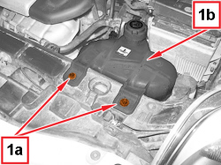  |
1. Undo the screws (1a) and move the engine cooling reservoir (1b) aside without disconnecting the pipes. |
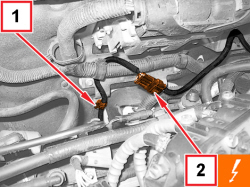  |
1. Open the multivalve retaining band shown in the figure. 2. Disconnect the electrical connection for the multivalve wiring.
|
|
|
- Release the multivalve wiring from the engine compartment. |
|
|
|
|
|
- Mark the position of the multivalve wiring retaining band and remove it. |
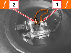  |
1. Disconnect the electrical connection for the LPG level gauge.
2. Disconnect the electrical connection for the LPG intake solenoid valve coil.
|
|
|
|
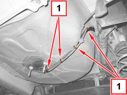  |
1. Mark the position of the multivalve wiring retaining bands and remove them. |
|
|
- Retain the rear section of the multivalve wiring through the pipe sleeve in the LPG tank compartment. |
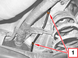  |
1. Mark the position of the wiring retaining bands for multivalves shown and remove them. |
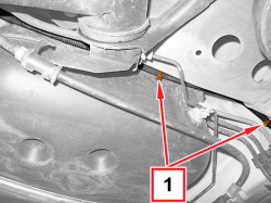  |
1. Mark the position of the wiring retaining bands for multivalves shown and remove them. |
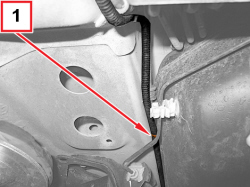  |
1. Mark the position of the multivalve wiring retaining band and remove it. |
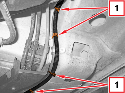  |
1. Mark the position of the wiring retaining bands for multivalves shown and remove them. |
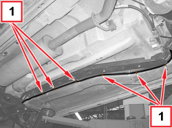  |
1. Mark the position of the wiring retaining bands for multivalves shown and remove them. |
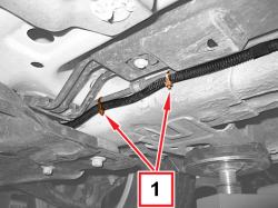  |
1. Mark the position of the wiring retaining bands for multivalves shown and remove them. |
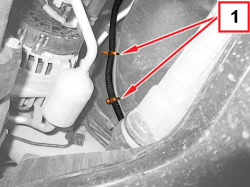  |
1. Mark the position of the wiring retaining bands for multivalves shown and remove them. |
|
|
- Remove the multivalve wiring. |
|
|
Refitting
(
Removing
)
- Insert the multivalve wiring through the pipe sleeve in the LPG tank compartment, starting from the connector, engine compartment side. |
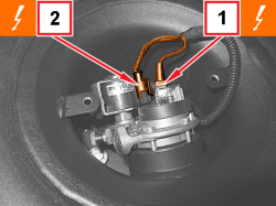  |
1. Connect the electrical connection for the LPG level gauge.
2. Connect the electrical connection for the LPG intake solenoid valve coil.
|
|
|
|
|
|
- Engage the multivalve wiring with the coil of the supply pipe to LPG pressure regulator with the band. |
|
|
- Fit the multivalve wiring between fuel vapour pipes and body, starting from the connector on engine compartment side connector . |
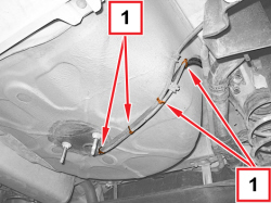  |
1. Engage the multivalve wiring in the LPG pipes with the bands. |
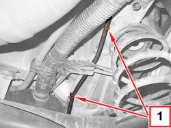  |
1. Engage the multivalve wiring in the supply pipe to LPG pressure regulator with the bands positioned as shown. |
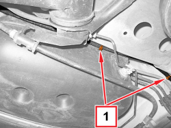  |
1. Engage the multivalve wiring in the supply pipe to LPG pressure regulator with the bands positioned as shown. |
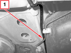  |
1. Engage the multivalve wiring in the supply pipe to LPG pressure regulator with the band positioned as shown. |
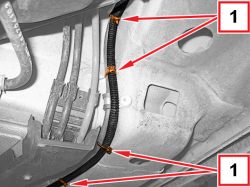  |
1. Engage the multivalve wiring in the supply pipe to LPG pressure regulator with the bands positioned as shown. |
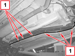  |
1. Engage the multivalve wiring in the supply pipe to LPG pressure regulator with the bands positioned as shown.
|
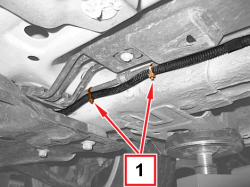  |
1. Engage the multivalve wiring in the supply pipe to LPG pressure regulator with the bands positioned as shown. |
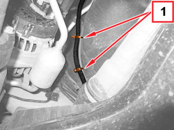  |
1. Engage the multivalve wiring in the supply pipe to LPG pressure regulator with the bands positioned as shown. |
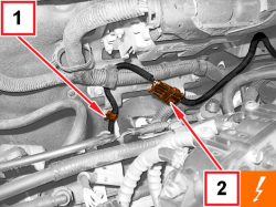  |
1. Engage the multivalve wiring in the retaining clip. 2. Connect the electrical connection for the multivalve wiring.
|
|
|
|
|
|
- Fit the engine cooling supply reservoir in place and secure it using the screws. |
|
|
- Connect the negative battery terminal. |
|
|
|
|
|
- Remove the vehicle from the lift. |
