
 Removing
(
Refitting
Removing
(
Refitting )
)
- Place the car on a lift.
- Disconnect the battery.
|
Name |
Connector | |
|
- |
BATTERY |
|
|
Removing
(
Refitting
)
- Place the car on a lift. - Disconnect the battery.
|
|
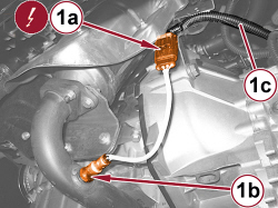  |
1. Disconnect the electrical connection (1a) for the oxygen sensor behind the catalytic converter (1b) and release the cable (1c).
|
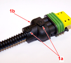  |
1. If fitted, work on the retaining clips (1a), then release the cable guide (1b) and remove it. |
  |
|
|
|
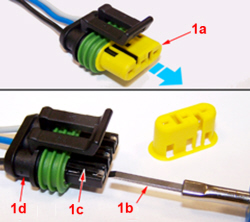
- To replace the terminals proceed as follows.
|
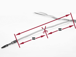  |
1. Release the cable for the terminal to be replaced sufficiently to work and cut at the midway point as illustrated in the figure. |
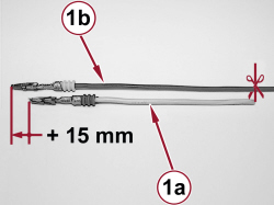  |
1. Measure the cable that has just been cut (1a), then cut the replacement cable (1b) 15 mm longer than the cable to be replaced. |
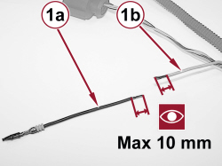  |
1. Strip the new replacement cable (1a) and the corresponding wiring cable (1b) for a maximum length of 10 mm. |
|
|
|
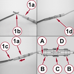  |
1. Fit the thermal restricting coupling tube (1a) on the wiring cable. Starting as illustrated in the figure (1b) twist the strands (1c), then move the coupling tube (1a) until the coupling is covered with the tin ring (1d) by the twisted strands (1c). A. Thermal shrinking coupling tube B. Adhesive ring C. Tin ring D. Twisted strands |
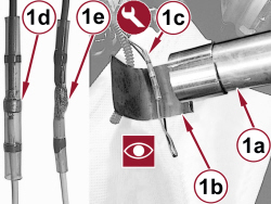  |
1. Using the drier (1a) fitted with the heat shield (1b) heat the thermal shrinking tube (1c) until the tin ring (1d) melts as illustrated in figure (1e). Wait for the tin to cool down, then refit the wiring.
|
|
|
Refitting
(
Removing
)
- Fit the terminal in the connector block checking that the retaining clip is secured. - Fit the terminal lock and the cable guide removed previously. - Slightly pull every single cable checking that the terminals are secured correctly. - Connect the electrical connection for the rear oxygen sensor to the catalytic converter. |
|
- Connect the battery. - Check the operation of the oxygen sensor using the diagnosis equipment. |

