145 - MiTo   1.4 16v TJet   HEADLAMP/LIGHT CLUSTER LIGHT BEAM - POSITION   5540B38   

Detail     Detail


Enlarge the image


- Equip the vehicle with spare wheel, tools, fluids, fuel reserve and with the driver on board.

- Check that the tyre inflation pressure is correct.

- Move the headlamp alignment to "0" position.

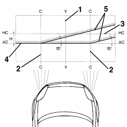
- Place the vehicle on a flat surface, perpendicular to a screen with an opaque surface 10 metres away on which the following lines are traced.

1. V-V: vertical, corresponding to the trace of vehicle plane of symmetry.

2. C-C: lines drawn through vertical planes passing through the light cluster reference centres.

3. HC-HC: horizontal, corresponding to the ground clearance of the light cluster reference centres.

4. AC-AC: horizontal, 10 cm below the line HC - HC.

5. Lines inclined by 15° as illustrated in the diagram.

Enlarge the image


- Switch on the dipped headlamps.

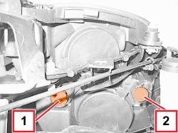
1. Vertical alignment. Adjust the vertical adjustment screw for the light cluster so that the horizontal section of the demarcation line between the dark zone and the area lit up by the light band is aligned with the line AC - AC traced on the screen.

2. Horizontal alignment. Adjust the horizontal adjustment screw for the light cluster so that the point where the two horizontal and inclined demarcation lines cross with the point where lines C - C and AC - AC cross on the screen is aligned.

APPLIES TO VERSIONS WITH: Gas discharge headlamps


Enlarge the image


- Equip the vehicle with spare wheel, tools, fluids, fuel reserve and with the driver on board.

- Check that the tyre inflation pressure is correct.

- Eseguire la calibrazione della posizione dei proiettori utilizzando Examiner o altra strumentazione diagnostica.

- Place the vehicle on a flat surface, perpendicular to a screen with an opaque surface 10 metres away on which the following lines are traced.

1. V-V: vertical, corresponding to the trace of vehicle plane of symmetry.

2. C-C: lines drawn through vertical planes passing through the light cluster reference centres.

3. HC-HC: horizontal, corresponding to the ground clearance of the light cluster reference centres.

4. AC-AC: horizontal, 10 cm below the line HC - HC.

5. Lines inclined by 15° as illustrated in the diagram.

APPLIES TO VERSIONS WITH: Gas discharge headlamps


Enlarge the image


- Switch on the dipped headlamps.

1. Vertical alignment. Adjust the vertical adjustment screw for the light cluster so that the horizontal section of the demarcation line between the dark zone and the area lit up by the light band is aligned with the line AC - AC traced on the screen.

2. Horizontal alignment. Adjust the horizontal adjustment screw for the light cluster so that the point where the two horizontal and inclined demarcation lines cross with the point where lines C - C and AC - AC cross on the screen is aligned.