145 - MiTo   1.4 16v TJet   ENGINE - DISMANTLING AND REASSEMBLY FOLLOWING OP.1004E10 - WASH AND CHECK DISMANTLED COMPONENTS - REFITTING CYLINDER HEAD AND OIL SUMP - DOES NOT INCLUDE OPERATIONS ON CYLINDER HEAD AND AUXILIARY UNITS   1004E20   

Detail     Detail


Enlarge the image


Removing ( Refitting )

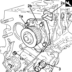
1. Undo the screws (1a) and the nut (1b) securing the water pump to the engine block.

2. Remove the sealant using the tool (2a) and remove the water pump (2b).


Tool


Name


Function


Validity


1870718000


Blade


Cut sealant


- Clean thoroughly between the engine block and water pump mating surfaces.

3. Remove the minimum engine oil pressure switch.


Enlarge the image


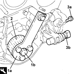
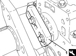
1. Fit the tool (1a) and undo the screw (1b) securing the crankshaft gear.


Tool


Name


Function


Validity


2000004500


Template


Crankshaft timing


1.4 8v

1.4 16v TJet

1.4 16v

1.4 MultiAir

1.4 Turbo MultiAir

- Remove the template fitted previously.

2. Remove the crankshaft gear.

3. Undo the screw (3a) and remove the rpm sensor (3b).


Enlarge the image


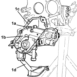
1. Undo the screws (1a) and remove the engine block front cover (1b) with built-in oil pump, complete with gasket (1c) and intake duct (1d).


Enlarge the image


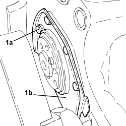
1. Undo the screws (1a) and remove the crankshaft rear cover (1b) with built-in oil seal ring.


Enlarge the image


- Rotate the engine block through 180°.

1. Fit the tool for rotating the crankshaft.


Tool


Name


Function


Validity


1860815000


Flange


Crankshaft rotation


Enlarge the image


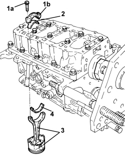
1. Undo the screws (1a) and remove the connecting rod caps (1b).

2. Remove the lower connecting rod half-bearings.

3. Remove the connecting rod - piston assemblies.

4. Remove the upper connecting rod half-bearings.

The arrow on the piston crown facing the timing side indicates the fitting direction.

The matching of the connecting rod-cap is the "BREAKING" type therefore the position is compulsory and the number corresponding to the position of the cylinder must be present.


Enlarge the image


- Remove the flange for rotating the crankshaft fitted previously.

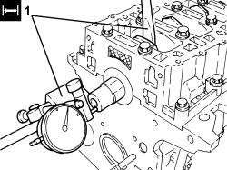
1. Using a dial gauge, check that the crankshaft end float is within specified limits.


Measurement


Value


Validity


Crankshaft end float (mm)


0,155 – 0,355


1.4 16v TJet

1.4 16v

1.4 MultiAir

1.4 Turbo MultiAir

- Remove the dial gauge.

If the value for the crankshaft end float does not correspond to the prescribed figures, when refitting, regrind the engine block seat and use the central main bearing half incorporating appropriately oversized crankshaft thrust half-washers.


Enlarge the image


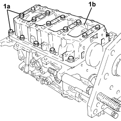
1. Undo the screws (1a) and remove the lower crankcase (1b), complete with lower half-bearings, from the engine block.


Enlarge the image


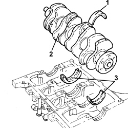
1. Remove the lower main half bearings from the engine block.

2. Remove the crankshaft.

3. Remove the upper main half-bearings.


Enlarge the image


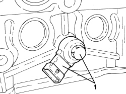
1. Undo the screw and remove the knock sensor.


Enlarge the image


- Remove the lower crankcase locating bushes with the engine block.

- Raise the engine block using a hydraulic lift and place it on a suitable workbench.

    Op. 1028H60 SET OF PISTONS, GUDGEON PINS AND RINGS - REPLACE PISTONS AND CONNECTING RODS AT THE BENCH - INCLUDES ALIGNMENT AND BALANCING

    Op. 1084B18 ENGINE OIL PUMP, REMOVED - CHECK AT THE BENCH

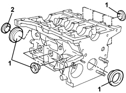
1. Remove the coolant chamber plugs from the engine block using an appropriate steel striker.

2. Remove the lubrication duct plug from the engine block using a steel striker.


Enlarge the image


1. Remove the oil jets (1a) using the tool (1b).


Tool


Name


Function


Validity


1860395000


Installer


Engine oil jet removal


1.4 8v

1.4 16v TJet

1.4 16v

1.4 MultiAir

1.4 Turbo MultiAir

Insert the striker guide hole on the nozzle surface to prevent the striker from slipping and damaging the cylinder liner during the removal operation.

Use new oil jets when refitting.


Enlarge the image


Refitting ( Removing )

- Wash and check the appearance of all components removed.

- Place the engine block on the overhaul stand.

- Fit the water/oil sealing plugs in the engine block using suitable fitting tools and sealant.

- Fit the locating bushes for the engine block.

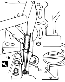
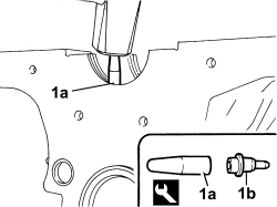
1. Use the tool (1a) and a plastic mallet to fit the new oil jets (1b).


Tool


Name


Function


Validity


1860313000


Fitting tool


Engine oil jet fitting


1.4 8v

1.4 16v TJet

1.4 16v

1.4 MultiAir

1.4 Turbo MultiAir


Enlarge the image


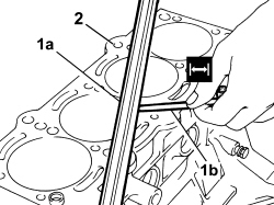
1. Using a calibrated metal rule (1a) and a feeler gauge (1b), check the flatness of the cylinder head - engine block support surface.

2. If the measurement does not correspond to the prescribed values, regrind the cylinder head support surface.


Measurement


Value


Validity


Engine cylinder head lower surface flatness (mm)


< 0.1


Enlarge the image


- Measure the diameter of the cylinder liners and check that they correspond to the prescribed figures.


Measurement


Value


Validity


Cylinder liner inner diameter - Class A (mm)


72,000 – 72,010


1.4 16v TJet

1.4 MultiAir

1.4 Turbo MultiAir


Measurement


Value


Validity


Cylinder liner inner diameter - Class B (mm)


72,010 – 72,020


1.4 16v TJet

1.4 MultiAir

1.4 Turbo MultiAir


Measurement


Value


Validity


Cylinder liner inner diameter - Class C (mm)


72,020 – 72,030


1.4 16v TJet

1.4 MultiAir

1.4 Turbo MultiAir

- Check that the ovality of the cylinder liners is within the prescribed limits.


Measurement


Value


Validity


Cylinder liner ovality (mm)


+/- 0.05


1.4 8v

1.4 16v TJet

1.4 16v

1.4 MultiAir

1.4 Turbo MultiAir

- Check that the taper of the cylinder liners is within the prescribed limits.


Measurement


Value


Validity


Cylinder liner taper (mm)


+/- 0,005


1.4 8v

1.4 16v TJet

1.4 16v

1.4 MultiAir

1.4 Turbo MultiAir

- If the cylinder bore, taper or ovality measurements are not within the prescribed limits, ream the cylinder bores following the prescribed oversizes.

In the case of reaming, all the liners must have the same oversize.


Measurement


Value


Validity


Cylinder liner inner diameter oversize (mm)


0.1


- Check that the diameter of the main journals is within the prescribed limits.


Measurement


Value


Validity


Main journal diameter - Grade A (mm)


47,994 – 48,000


0.9 TwinAir

1.4 16v TJet

1.4 MultiAir

1.4 Turbo MultiAir


Measurement


Value


Validity


Main journal diameter - Grade B (mm)


47,988 – 47,994


0.9 TwinAir

1.4 16v TJet

1.4 MultiAir

1.4 Turbo MultiAir


Measurement


Value


Validity


Main journal diameter - Grade C (mm)


47,982 – 47,988


0.9 TwinAir

1.4 16v TJet

1.4 MultiAir

1.4 Turbo MultiAir

- If the diameter of the main journals does not fall within the prescribed values, they should be reground to the prescribed undersize.

Because the crankshaft has undergone nitriding, this treatment should be repeated and the size re-checked if it is ground.


Measurement


Value


Validity


Main journal diameter undersize (mm)


0,127


- Check that the diameter of the crankpins is within the prescribed limits.


Measurement


Value


Validity


Crankpin diameter (mm)


41,990 – 42,008


1.4 8v

1.4 16v TJet

1.4 16v

1.4 MultiAir

1.4 Turbo MultiAir

- If the diameter of the crankpins is not correct, they should be reground to the prescribed undersize.

Because the crankshaft has undergone nitriding, this treatment should be repeated and the size re-checked if it is ground.


Measurement


Value


Validity


Crankpin diameter undersize (mm)


0,127


- Check the main bearings, noting that the half-bearings should not be adapted. Replace them if scoring or signs of binding are found.

- Fit the main bearing halves in their seats on the upper crankcase, aligning the lubrication ports and ensuring scrupulous cleanliness. The centre main bearing half incorporates the thrust half-washers because it performs a load-bearing function and also acts as a thrust bearing.

- If the crankshaft has been ground, fit new oversize half-bearings to restore the initial tolerance conditions.

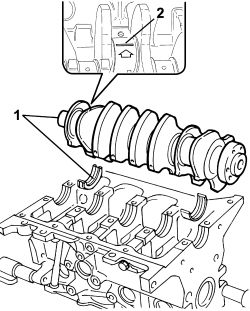
1. Fit the crankshaft in the special housing in the engine block with the upper half-bearings.

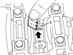
2. Fit the calibrated wire (Plastigage) for measuring the main journal clearance.


Enlarge the image


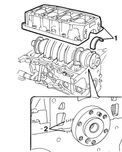
1. Fit the main half-bearings in the lower crankcase.

2. Fit the lower crankcase on the engine block, checking that the codes stamped on both parts of the engine block correspond, because the engine block components are not interchangeable.


Enlarge the image


- The size of the main half-bearings is given.


Measurement


Value


Validity


Main half-bearings - Grade 1 (Red) (mm)


1,836 – 1,840


1.4 8v

1.4 16v TJet

1.4 16v

1.4 MultiAir

1.4 Turbo MultiAir


Measurement


Value


Validity


Main half-bearings - Grade 2 (Blue) (mm)


1,843 – 1,847


1.4 8v

1.4 16v TJet

1.4 16v

1.4 MultiAir

1.4 Turbo MultiAir


Measurement


Value


Validity


Main half-bearings - Grade 3 (Yellow) (mm)


1,848 – 1,852


1.4 8v

1.4 16v TJet

1.4 16v

1.4 MultiAir

1.4 Turbo MultiAir


Measurement


Value


Validity


Main bearing half undersize (mm)


0,127


1.4 16v TJet

1.4 16v

1.4 MultiAir

1.4 Turbo MultiAir

- Tighten the screws securing the lower crankcase to the engine block to the prescribed torque.


Component


Fastening


Ø


Value (daNm)


Validity


Crankcase


Central screw


M10


1.9 ÷ 2.1 + 80°


1.4 16v TJet

1.4 MultiAir

1.4 Turbo MultiAir


Component


Fastening


Ø


Value (daNm)


Validity


Crankcase


Side screw


M8


2.9 – 3.2


1.4 16v TJet

1.3 Multijet

1.4 MultiAir

1.4 Turbo MultiAir

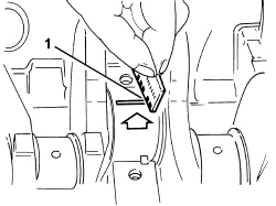
1. Remove the lower crankcase and check the main journal clearance. Use an appropriate measuring device to measure the width of the calibrated wire.

Check one main journal at a time, without rotating the crankshaft.


Measurement


Value


Validity


Clearance between main bearings - crankshaft main journals (mm)


0,025 – 0,040


1.4 8v

1.4 16v TJet

1.4 16v

1.4 MultiAir

1.4 Turbo MultiAir


Enlarge the image


- After checking all the main journals, apply sealant to the contact surfaces between the lower crankcase and upper crankcase. Then fit the lower crankcase permanently by tightening the screws to torque in the order described previously.

Apply a 2-mm thick continuous sealant strip to the lower crankcase surface.

- Check that the outer diameter of the pistons corresponds to the prescribed figures; if not, replace the pistons complete with sealing rings and piston pins.


Measurement


Value


Validity


Piston outer diameter - Class A (mm)


71,960 – 71,970


1.4 8v

1.4 16v TJet

1.4 16v

1.4 MultiAir

1.4 Turbo MultiAir


Measurement


Value


Validity


Piston outer diameter - Class B (mm)


71,970 – 71,980


1.4 8v

1.4 16v TJet

1.4 16v

1.4 MultiAir

1.4 Turbo MultiAir


Measurement


Value


Validity


Piston outer diameter - Class C (mm)


71,980 – 71,990


1.4 8v

1.4 16v TJet

1.4 16v

1.4 MultiAir

1.4 Turbo MultiAir

Measure perpendicular to the gudgeon pin axis, 9 mm from the lower edge of the skirt.

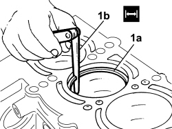
- Position the pistons in the cylinder liners and use a feeler gauge to measure the specified clearance.


Measurement


Value


Validity


Clearance between piston - cylinder liner (mm)


0,030 – 0,050


1.4 16v TJet

1.4 16v

1.4 MultiAir

1.4 Turbo MultiAir

- Check that the inner bore of the piston pin housings is within the prescribed limits; if not, replace the pistons.


Measurement


Value


Validity


Gudgeon pin housing diameter (mm)


17,978 – 17,982


1.4 16v TJet

1.4 Turbo MultiAir

- Check that the outer diameter of the piston pins is within the prescribed limits; if not, replace the worn parts.


Measurement


Value


Validity


Gudgeon pin outer diameter (mm)


17,970 – 17,974


1.4 8v

1.4 16v TJet

1.4 MultiAir

1.4 Turbo MultiAir

- Use a micrometer gauge to measure the thickness of the piston sealing rings.


Measurement


Value


Validity


Cylinder compression 1st sealing ring thickness (mm)


1,170 – 1,195


1.4 16v TJet

1.4 Turbo MultiAir


Measurement


Value


Validity


Cylinder compression 2nd sealing ring thickness (mm)


1,170 – 1,190


1.4 16v TJet

1.4 Turbo MultiAir


Measurement


Value


Validity


Cylinder compression 3rd sealing ring thickness (mm)


1,970 – 1,990


1.4 16v TJet

1.4 Turbo MultiAir


Measurement


Value


Validity


Sealing ring oversize (mm)


0.1


1.4 8v

1.4 16v TJet

1.4 16v

1.4 MultiAir

1.4 Turbo MultiAir

1. Fit the sealing rings (1a) in the cylinder liners/bores and use a feeler gauge (1b) to check the gap between the seal ends is within specified limits. Otherwise replace the sealing rings.


Measurement


Value


Validity


Cylinder compression 1st sealing ring gap (mm)


0.20 – 0.35


1.4 16v TJet

1.4 MultiAir

1.4 Turbo MultiAir


Measurement


Value


Validity


Cylinder compression 2nd sealing ring gap (mm)


0.40 – 0.60


1.4 16v TJet

1.4 MultiAir

1.4 Turbo MultiAir


Measurement


Value


Validity


Cylinder compression 3rd sealing ring gap (mm)


0.20 – 0.40


1.4 16v TJet

1.4 MultiAir

1.4 Turbo MultiAir


Enlarge the image


- Check that the diameters of the big ends and the small ends are within the prescribed values.


Measurement


Value


Validity


Big end diameter (mm)


45,128 – 45,138


1.4 16v TJet

1.4 16v

1.4 MultiAir

1.4 Turbo MultiAir


Measurement


Value


Validity


Small end diameter with bush (mm)


17,993 – 18,000


1.4 16v TJet

1.4 Turbo MultiAir

The small end bush cannot be separated from the actual connecting rod.

The bush is therefore handled by the Parts Dept. together with the connecting rod.

    Op. 1028H60 SET OF PISTONS, GUDGEON PINS AND RINGS - REPLACE PISTONS AND CONNECTING RODS AT THE BENCH - INCLUDES ALIGNMENT AND BALANCING

    Op. 1084B18 ENGINE OIL PUMP, REMOVED - CHECK AT THE BENCH

- Fit the tool for rotating the crankshaft.


Tool


Name


Function


Validity


1860815000


Flange


Crankshaft rotation


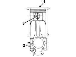
- Fit the connecting rod-piston assemblies and align in accordance with the following references.

1. Piston class and arrow indicating timing side.

2. Area on the inlet side where the number indicating the cylinder to which the connecting rod belongs is stamped.

3. Gudgeon pin offset


Enlarge the image


The matching of the connecting rod-cap is "BREAKING" type therefore the position is compulsory and the number corresponding to the position of the cylinder must be present.

Letters identifying the cylinder liner classes are shown on the engine block.

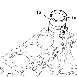
1. Fit the connecting rod/piston assemblies (1a) with half-bearings, using tool (1b) to compress retaining rings and then fit the piston into the liner.


Enlarge the image


- Rotate the engine on the overhaul stand.

1. Apply the calibrated wire (Plastigage) for measuring the crankpin clearance.

- The size of the connecting rod half-bearings is given.


Measurement


Value


Validity


Connecting rod half-bearing thickness (mm)


1,544 – 1,548


1.4 8v

1.4 16v TJet

1.4 16v

1.4 MultiAir

1.4 Turbo MultiAir


Measurement


Value


Validity


Connecting rod half-bearing 1 oversize (mm)


0,127


1.4 16v TJet

1.4 MultiAir

1.4 Turbo MultiAir


Measurement


Value


Validity


Connecting rod half-bearing 2 oversize (mm)


0,254


1.4 16v TJet

1.4 MultiAir

1.4 Turbo MultiAir


Measurement


Value


Validity


Connecting rod half-bearing 3 oversize (mm)


0,508


1.4 16v TJet

1.4 MultiAir

1.4 Turbo MultiAir


Enlarge the image


- Refit the connecting rod caps complete with half-bearings and secure them by tightening the screws to the prescribed torque.

The connecting rod caps are fracture type. If replaced, they are supplied pre-fractured by the manufacturer. Check that the parts are free of burrs, blisters, scratches or any other surface defect. Before installation, parts must be thoroughly washed, cleaned and dried. Fit the connecting rod caps so that the number stamped on each cap faces towards the same side as the number stamped on the big end.

Each connecting rod must be paired with its cap, respecting the numerical references stamped on the parts. Connecting rods and connecting rod caps are not interchangeable.


Component


Fastening


Ø


Value (daNm)


Validity


Connecting rod caps


Screw


M8


1.9 - 2.1 + 40° +/- 2°


1.4 8v

1.4 16v TJet

1.4 16v

1.3 Multijet

1.4 MultiAir

1.4 Turbo MultiAir

1. Remove the connecting rod caps and check the crankpin clearance. Use an appropriate gauge to measure the width of the calibrated wire.

Check one crankpin at a time, without rotating the crankshaft.


Measurement


Value


Validity


Clearance between connecting rod bearings - crankshaft crankpins (mm)


0,024 – 0,060


1.4 16v TJet

1.4 MultiAir

1.4 Turbo MultiAir

- If the value measured is not within the prescribed figures, replace the connecting rod bearings.


Enlarge the image


- Refit the connecting rod caps complete with half-bearings and secure them by tightening the screws to the torque given previously.

- Rotate the engine on the overhaul stand.

- Position a new oil pump gasket.

- Fit the front engine block cover with built-in oil pump complete with intake chamber and secure by tightening the screws to the prescribed torque.


Component


Fastening


Ø


Value (daNm)


Validity


Engine oil pump


Screw


M6


0.9 – 1.1


1.4 16v TJet

1.4 16v

1.4 MultiAir

1.4 Turbo MultiAir

- Place the minimum engine oil pressure switch in position and tighten it to the prescribed torque.


Component


Fastening


Ø


Value (daNm)


Validity


Engine oil pressure warning light switch


-


M14


3.2


1.4 16v TJet

1.4 16v

1.4 MultiAir

1.4 Turbo MultiAir

- Fit the oil seal on the crankshaft front cover using the tool.


Tool


Name


Function


Validity


1860990000


Fitting tool


Fitting oil seal


1.4 8v

1.4 16v TJet

1.4 16v

1.4 MultiAir

1.4 Turbo MultiAir

- Remove the flange for rotating the crankshaft fitted previously.

- Place a new engine block rear cover with integrated oil seal ring in position and secure it by tightening the screws to the prescribed torque.


Component


Fastening


Ø


Value (daNm)


Validity


Crankshaft rear cover to engine block


Screw


M6


0.8 – 1.0


1.4 8v

1.4 16v TJet

1.4 16v

1.6 JTD 16v

1.4 MultiAir

1.4 Turbo MultiAir

- Place the crankshaft gear in its housing.

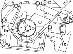
1. Because the timing is adjusted with the four pistons in line, i.e. half-way along their effective strokes, it is essential to position the crankshaft timed with the camshafts. They can be approximately positioned by turning the crankshaft gear (1a) until the locating dowel (1b) is positioned opposite to the rpm sensor seat (1c) with the first cylinder piston in descending phase, i.e. intake.


Enlarge the image


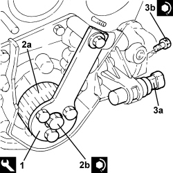
1. Position the counter-torque tool.


Tool


Name


Function


Validity


2000004500


Template


Crankshaft timing


1.4 8v

1.4 16v TJet

1.4 16v

1.4 MultiAir

1.4 Turbo MultiAir

2. Secure the crankshaft gear (2a) by tightening the screw (2b) to the prescribed torque.


Component


Fastening


Ø


Value (daNm)


Validity


Crankshaft gear


Screw


M12


1.9 - 2.1 + 107° - 113°


1.4 16v TJet

1.4 16v

1.4 MultiAir

1.4 Turbo MultiAir

3. Position the rpm sensor (3a) in its housing and secure it by tightening the screw (3b) to the prescribed torque.


Component


Fastening


Ø


Value (daNm)


Validity


Rpm sensor


Screw


M6


0.8 – 1.0


1.4 8v

1.4 16v TJet

1.4 MultiAir

1.4 Turbo MultiAir


Enlarge the image


- Apply silicone sealant to the splining on the flange securing the water pump to the engine block.

- Position the water pump in its housing and secure it, tightening the screws and the nut to the prescribed torque.


Component


Fastening


Ø


Value (daNm)


Validity


Water pump


Screw


M6


0.9 – 1.1


1.4 16v TJet

1.4 8v

1.4 16v

1.4 MultiAir

1.4 Turbo MultiAir


Component


Fastening


Ø


Value (daNm)


Validity


Water pump


Nut


M6


0.9 – 1.1


1.4 16v TJet

1.4 8v

1.4 16v

1.4 MultiAir

1.4 Turbo MultiAir

- Rotate the engine through 180° on the overhaul stand.

- Clean the lower crankcase and oil sump contact surfaces, removing the silicone sealant residues.

- Apply the sealant without a break to the entire perimeter of the oil sump.

- Position the oil sump in its housing and secure it, tightening the screws and the nuts to the prescribed torque.

When positioning the oil sump, avoid significant sideways movements that could remove the sealant.


Component


Fastening


Ø


Value (daNm)


Validity


Engine oil sump


Screw


M6


0.8 – 1.0


1.4 16v TJet

1.4 16v

1.4 MultiAir

1.4 Turbo MultiAir


Component


Fastening


Ø


Value (daNm)


Validity


Engine oil sump


Nut


M6


0.8 – 1.0


1.4 8v

1.4 16v TJet

1.4 16v

1.4 MultiAir

1.4 Turbo MultiAir

- Rotate the engine through 180° on the overhaul stand.

- Fit the locating bushes for the engine block.

- Fit a new cylinder head gasket on the engine block.

- Position the cylinder head on the engine block, aligning the locating dowels.

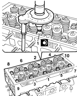
1. Tighten the screws securing the cylinder head to the prescribed torque.

Follow the order shown in the diagram for each tightening sequence.


Component


Fastening


Ø


Value (daNm)


Validity


Cylinder head


Screw


M9


3.0 + 90°+ 90°


1.4 16v TJet

1.4 16v

1.4 MultiAir

1.4 Turbo MultiAir

- Fit the locating bushes and position the camshaft housing seal on the cylinder head support plane.

- Position the tappet retaining tools beneath the camshaft housing, then place the camshaft housing on the cylinder head and withdraw the tools.

- Use the tool to tighten the camshaft housing screws to the prescribed torque.


Tool


Name


Function


Validity


1860834000


Spanner


Loosen/tighten upper cylinder head screws

Undo/tighten crankcase sump side screws


1.4 16v TJet

1.4 16v

1.6 JTD 16v


Component


Fastening


Ø


Value (daNm)


Validity


Camshaft housing


Screw


M8


1.3 – 1.6


1.4 16v TJet

1.4 16v

1.4 MultiAir

1.4 Turbo MultiAir

- Refit the plugs complete with new O-rings and tighten them to the prescribed torque.


Component


Fastening


Ø


Value (daNm)


Validity


Camshaft housing plugs


Plugs


M16


1.3 – 1.6


1.4 16v TJet

1.4 16v

- Place the camshaft driven pulley in its housing without tightening the screw.

- Fit the camshaft driven pulley locking tool.


Tool


Name


Function


Validity


2000015800


Counter-torque


Locking driven pulley


1.4 16v TJet

1.4 16v

- Tighten the camshaft driven pulley screw to the prescribed torque.


Component


Fastening


Ø


Value (daNm)


Validity


Driven timing pulley


Screw


M12


10.8 – 13.2


1.4 16v TJet

1.4 16v

1.4 MultiAir

1.4 Turbo MultiAir

- Tighten the retaining screws for the camshaft idler gears to the prescribed torque.


Component


Fastening


Ø


Value (daNm)


Validity


Camshaft gears


Screw


M12


12.0


1.4 16v TJet

1.4 16v

- Loosen the screw securing the camshaft driven pulley and remove the locking tool.


Enlarge the image


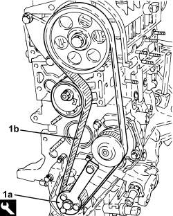
1. After fitting the tool (1a), proceed with fitting the timing drive belt (1b), fitting it at first on the crankshaft gear, on the water pump pulley, on the camshaft driven pulley and lastly on the mobile tensioner.


Tool


Name


Function


Validity


2000004500


Template


Crankshaft timing


1.4 8v

1.4 16v TJet

1.4 16v

1.4 MultiAir

1.4 Turbo MultiAir

Ensure that this operation is performed with the camshaft driven pulley slack.

- Camshaft timing was adjusted previously by applying special tools.


Tool


Name


Function


Validity


1860985000


Locating pins


Camshaft timing


1.4 16v TJet

1.4 16v


Enlarge the image


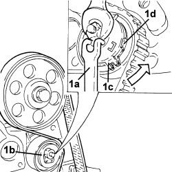
1. Tension the timing belt by turning it counterclockwise with the tool (1a) and the moving tensioner (1b) and then secure it when the reference fork (1c) touches the striker (1d).


Tool


Name


Function


Validity


1860987000


Spanner


Tensioning toothed timing drive belt


1.4 16v TJet

1.4 8v

1.4 16v

1.4 MultiAir

1.4 Turbo MultiAir


Enlarge the image


- Fit the camshaft driven pulley locking tool.


Tool


Name


Function


Validity


2000015800


Counter-torque


Locking driven pulley


1.4 16v TJet

1.4 16v

- Tighten the camshaft driven pulley screw to the prescribed torque.


Component


Fastening


Ø


Value (daNm)


Validity


Driven timing pulley


Screw


M12


10.8 – 13.2


1.4 16v TJet

1.4 16v

1.4 MultiAir

1.4 Turbo MultiAir

- Remove the tools previously fitted for timing and make the crankshaft turn for two revolutions.

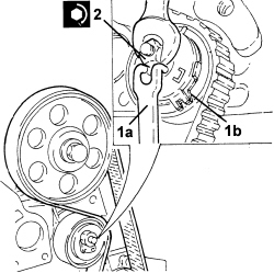
1. Loosen the moving tensioner nut and adjust the front fork using the tool (1a) until it is aligned with the rear fork (1b).

2. Tighten the nut securing the moving tensioner to the prescribed torque.


Component


Fastening


Ø


Value (daNm)


Validity


Timing control moving tensioner


Nut


M8


2.2 – 2.7


1.4 16v TJet

1.4 16v

1.4 MultiAir

1.4 Turbo MultiAir

- Turn the crankshaft through two revolutions in its normal rotation direction, then reposition the tools used to adjust timing and check the engine is timed.

- Remove the tools used for timing the engine.

- Place the side plugs in their seats in the camshaft housing and tighten them to the prescribed torque.


Component


Fastening


Ø


Value (daNm)


Validity


Camshaft housing plugs


Plugs


M16


1.3 – 1.6


1.4 16v TJet

1.4 16v

- Place the flywheel side camshaft seal rear cover in its housing and secure it using the nuts.

- Place the water pump inlet pipe, complete with a new gasket, in position and secure it by tightening the screws to the engine block and to the cylinder head to the prescribed torque.


Component


Fastening


Ø


Value (daNm)


Validity


Water pump inlet pipe


Screw


M6


0.9 – 1.1


1.4 16v TJet

1.4 16v

- Fit the ignition coils and tighten them to the prescribed torque.


Component


Fastening


Ø


Value (daNm)


Validity


Ignition coils


Screw


M6


0.9


1.4 16v TJet

1.4 8V

1.4 16v

1.4 MultiAir

1.4 Turbo MultiAir

- Position the timing sensor in its housing and secure it using the screw.

- Place the timing side engine rigid support in position and secure it by tightening the screws to the prescribed torque.


Component


Fastening


Ø


Value (daNm)


Validity


Timing side power unit rigid support


Screw


M8


2.2 – 2.7


1.4 16v TJet

1.4 16v

1.4 MultiAir

1.4 Turbo MultiAir

- Fit the upper and lower timing belt covers and secure them using the screws.

- Position the crankshaft pulley in its housing and secure it by tightening the screws to the prescribed torque.


Component


Fastening


Ø


Value (daNm)


Validity


Service pulley on crankshaft


Screw


M8


2.3 – 2.8


- Place the oil filter mounting and engine oil heat exchanger in position and tighten the connector, crankshaft oil seal front cover side, to the prescribed torque.


Component


Fastening


Ø


Value (daNm)


Validity


Heat exchanger and oil filter mounting - oil pump side


Screw


M20


4.1 – 4.5


1.4 16v TJet

- Tighten the screw securing the engine oil heat exchanger and oil filter mounting assembly, engine block side, to the prescribed torque.


Component


Fastening


Ø


Value (daNm)


Validity


Heat exchanger and oil filter mounting - engine block side


Screw


M10


4.5 – 5.5


1.4 16v TJet

1.4 MultiAir

1.4 Turbo MultiAir

- Place the exhaust manifold-turbocharger assembly, complete with new gasket, back in its housing and secure it by tightening the new nuts to the prescribed torque.


Component


Fastening


Ø


Value (daNm)


Validity


Exhaust manifold


Nut


M8


1.4 - 1.6 + 30° +/- 3°


1.4 16v TJet

1.4 16v

- Place the exhaust manifold heat shield in its housing and tighten the nuts to the prescribed torque.


Component


Fastening


Ø


Value (daNm)


Validity


Exhaust manifold heat shield


Nut (to be replaced)


M6


0.8 – 1.0


1.4 16v TJet

1.4 MultiAir

1.4 Turbo MultiAir

0.9 TwinAir

- Place the turbocharger coolant return pipe, complete with new gaskets, in position and tighten the connectors.

The connectors should be tightened keeping the pipe still. Any movement of the pipe of more than 3° will adversely affect the seal of the connectors.

- Place the turbocharger lubrication oil supply pipe, complete with new gasket, back in its housing and tighten the connectors to the prescribed torque.

The connectors should be tightened keeping the pipe still. Any movement of the pipe of more than 3° will adversely affect the seal of the connectors.


Component


Fastening


Ø


Value (daNm)
 

Validity


Engine oil supply pipe to turbocharger - heat exchanger side


Connector


M6


0.8 – 1.0


1.4 16v TJet

1.4 Turbo MultiAir


Component


Fastening


Ø


Value (daNm)


Validity


Engine oil pipe to turbocharger - turbocharger side


Connector


M12


1.8 – 2.2


1.4 16v TJet

- Tighten the screw securing the turbocharger lubrication oil supply pipe intermediate mounting bracket.

- Place the engine oil heat exchanger coolant return pipe, complete with new gaskets, in position and tighten the connectors.

The connectors should be tightened keeping the pipe still. Any movement of the pipe of more than 3° will adversely affect the seal of the connectors.

- Place the engine oil heat exchanger coolant delivery pipe, complete with new gaskets, in position and tighten the connectors to the prescribed torque.

The connectors should be tightened keeping the pipe still. Any movement of the pipe of more than 3° will adversely affect the seal of the connectors.


Component


Fastening


Ø


Value (daNm)


Validity


Coolant supply pipe to engine oil heat exchanger


Connector


M16


3.0 – 3.6


1.4 16v TJet

1.4 MultiAir

1.4 Turbo MultiAir

- Tighten the screws securing the coolant delivery pipe to the engine oil heat exchanger, engine block side and heat exchanger side.

- Place the turbocharger lubrication oil return pipe, complete with new gaskets, back in its housing and tighten the screws to the prescribed torque.

Tighten the "slotted screw" first when connecting the pipe to the turbocharger.

The connectors should be tightened keeping the pipe still. Any movement of the pipe of more than 3° will adversely affect the seal of the connectors.


Component


Fastening


Ø


Value (daNm)


Validity


Engine oil return pipe from turbocharger


Screw


M6


0.8 – 1.0


1.4 16v TJet

1.4 Turbo MultiAir

0.9 TwinAir

- Tighten the intermediate connector securing the turbocharger lubrication oil return pipe to the engine block, engine oil heat exchanger side, to the prescribed torque.

The connector should be tightened keeping the pipe still. Any movement of the pipe of more than 3° will adversely affect the seal of the connector.


Component


Fastening


Ø


Value (daNm)


Validity


Engine oil return pipe from turbocharger - oil filter mounting side


Connector


M16


3.0 – 3.6


1.4 16v TJet

1.4 Turbo MultiAir

- Place the water-engine oil heat exchanger heat shield in its housing and tighten the screws to the prescribed torque.

- Place the engine oil filter heat shield in its housing and tighten the screws to the prescribed torque.


Component


Fastening


Ø


Value (daNm)


Validity


Engine oil filter heat shield


Screw


M6


0.8 – 1.0


1.4 16v TJet

- Refit the bracket complete with pressurized air by-pass solenoid and tighten the fastenings.

- Refit the oil vapour separator and tighten the screws.

- Refit the air chamber in its seat and tighten the new screws to the prescribed torque.


Component


Fastening


Ø


Value (daNm)


Validity


Air intake chamber


Screw (to be replaced)


M7


1.3 – 1.6


1.4 16v TJet

1.4 MultiAir

1.4 Turbo MultiAir

- Connect the oil vapour supply pipe to the air chamber and tighten the band.

- Place the air chamber mounting bracket in position and tighten the screws.

- Place the engine oil dipstick pipe back in its housing and secure it with the screw.

- Place the intermediate shaft bearing support in position and secure it by tightening the screws to the prescribed torque.


Component


Fastening


Ø


Value (daNm)


Validity


Intermediate driveshaft bearing support


Screw


M8


2.3 – 2.8


1.4 16v TJet

1.4 MultiAir

1.4 Turbo MultiAir

- Fit the alternator and air conditioning compressor mounting in position and tighten the fastenings to the prescribed torque.

- Place the alternator in position and tighten the relevant screws.

- Place the air conditioning compressor in position and tighten the screws.

- Fit the auxiliary drive belt, adjust the moving tensioner and then remove the locking pin.

- Place the engine wiring back in position and tighten the screw securing the ignition coil wiring duct.

- Connect the electrical connections for the ignition coils.

- Secure the electrical connection for the timing sensor.

- Connect the earth lead and tighten the screw.

- Connect the electrical connection for the engine coolant temperature sensor.

- Connect the electrical connection for the pressurized air by-pass solenoid valve.

- Connect the electrical connection for the throttle body.

- Connect the wiring duct to the air chamber using the retaining clips.

- Connect the electrical connection for the fuel vapour solenoid valve.

- Connect the electrical connection for the knock sensor.

- Connect the injector wiring junction.

- Connect the electrical connection for the air conditioning compressor.

- Connect the alternator earth lead and tighten the nut.

- Place the timing belt inner guard in its housing and secure it using the screws.

- Connect the earth lead to the auxiliary support and tighten the screw.

- Connect the electrical connection for the air temperature and pressure sensor.

- Connect the electrical connection for the exhaust gas temperature sensor.

- Connect the electrical connection for the minimum engine oil pressure switch.

- Connect the electrical connection for the engine rpm sensor.