

 Refitting
(
Removing
Refitting
(
Removing )
)
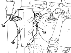
1. Undo the screws (1a) and remove timing belt inner guard (1b).
|
|
Refitting
(
Removing
)
1. Undo the screws (1a) and remove timing belt inner guard (1b). |
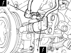  |
1. Disconnect the electrical connection for the engine rpm sensor.
2. Disconnect the electrical connector for the minimum engine oil pressure switch.
|
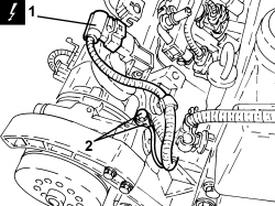  |
1. Disconnect the electrical connection for the air temperature and pressure sensor.
2. Undo the screw and remove the earth lead from the auxiliary support. |
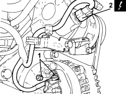  |
1. Undo the nut and remove the alternator earth lead. 2. Detach the electrical connection for the air conditioning compressor.
|
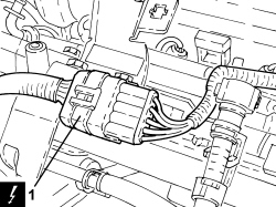  |
1. Disconnect the injector wiring coupling.
|
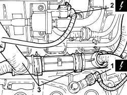  |
1. Disconnect the electrical connection for the knock sensor.
2. Disconnect the electrical connector for the fuel vapour solenoid valve.
3. Open the retaining clips and move the wiring to one side. |
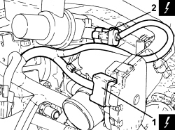  |
1. Detach the electrical connection for the throttle body.
2. Disconnect the electrical connection for the pressurized air by-pass solenoid valve.
|
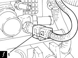  |
1. Disconnect the electrical connection for the engine coolant temperature sensor.
|
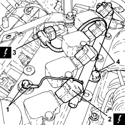  |
1. Undo the screw and remove the earth lead. 2. Disconnect the electrical connections for the ignition coils.
3. Detach the timing sensor electrical connection.
4. Undo the screw and remove the engine wiring. |
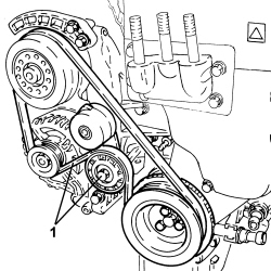  |
1. Adjust the moving tensioner, lock it using a suitable pin and remove the auxiliary drive belt. |
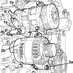  |
1. Undo the screws (1a) and remove the air conditioner compressor (1b). 2. Undo the screws (2a) and remove the alternator (2b). |
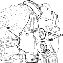  |
1. Undo fastenings (1a) and remove alternator and air conditioning compressor mounting (1b) complete with moving tensioner. |
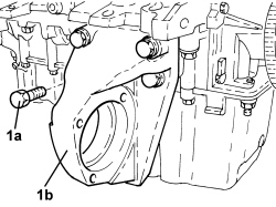  |
1. Undo the screws (1a) and remove the intermediate shaft bearing support (1b). |
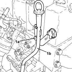  |
1. Undo the screw (1a) and remove the engine oil dipstick tube (1b). |
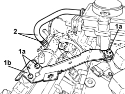  |
1. Undo the screws (1a) and remove the bracket (1b). 2. Loosen the band and remove the oil vapour supply pipe to the air chamber. |
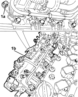  |
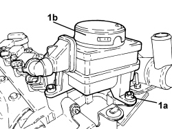
1. Undo the screws (1a) and remove the air chamber (1b). |
  |
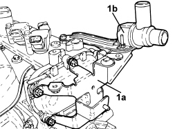
1. Undo the screws (1a) and remove the oil vapour separator (1b). |
  |
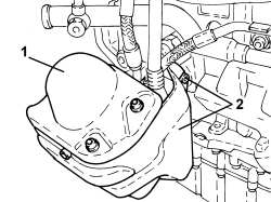
1. Undo the fastenings and remove bracket (1a) complete with pressurized air by-pass solenoid (1b). |
  |
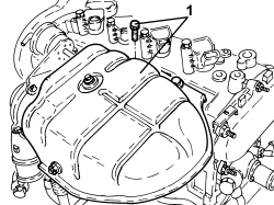
1. Unscrew the screws and remove the engine oil filter heat shield. 2. Undo the screws and remove the water-engine oil heat exchanger heat shield. |
  |
1. Undo the fastenings and remove the turbocharger heat shield. |
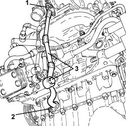  |
1. Undo the screws securing the turbocharger lubrication oil return pipe to the engine block, turbocharger side. 2. Undo the screws securing the turbocharger lubrication oil return pipe to the engine block, engine block side. 3. Undo the intermediate connector securing the turbocharger lubrication oil return pipe to the engine block, engine oil heat exchanger side and remove it. |
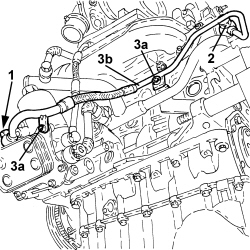  |
1. Unscrew the connector for the water delivery pipe to the engine oil heat exchanger, heat exchanger side. 2. Unscrew the connector for the water delivery pipe to the engine oil heat exchanger, thermostat side. 3. Undo the screw (3a) and remove the water delivery pipe to engine oil heat exchanger (3b). |
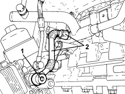  |
1. Unscrew the connector for the water return pipe from the engine oil heat exchanger, heat exchanger side. 2. Undo the connector for the water return pipe from the engine oil heat exchanger, return pipe side, to the water pump and remove it. |
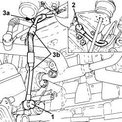  |
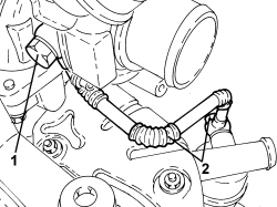
1. Undo the connector for the turbocharger lubrication oil supply pipe, heat exchanger side. 2. Undo the turbocharger lubrication oil supply pipe connector, turbocharger side. 3. Undo the screw securing the turbocharger lubrication oil supply pipe intermediate bracket and remove it. |
  |
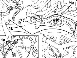
1. Undo the turbocharger coolant return pipe connector, turbocharger side. 2. Undo the turbocharger coolant return pipe connector, return pipe side, to the water pump and remove it. |
  |
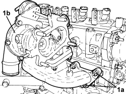
1. Undo nuts (1a) and remove the exhaust manifold heat shield (1b). |
  |
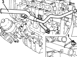
1. Undo nuts (1a) and remove the exhaust manifold-turbocharger assembly (1b). |
  |
1. Undo the screw securing the water pump return pipe, cylinder head side. 2. Undo the screw securing the water pump return pipe, engine block side. 3. Remove the return pipe to the water pump complete with seal ring. |
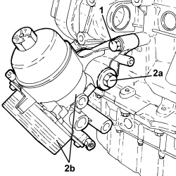  |
1. Undo the screw securing the oil filter mounting and engine oil heat exchanger assembly, engine block side. 2. Undo the connector (2a) securing oil filter mounting and engine oil heat exchanger assembly (2b), engine block front oil seal cover side, and remove it. |
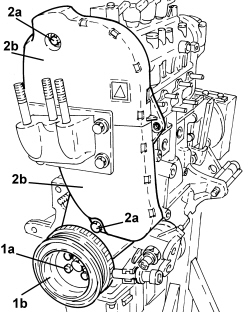  |
1. Undo the screws (1a) and remove the crankshaft pulley (1b). 2. Undo the screws (2a) and remove the timing belt protective covers (2b). |
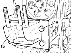  |
1. Undo the screws (1a) and remove the power unit rigid support (1b). |
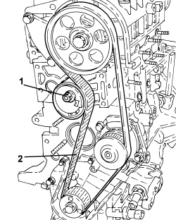  |
1. Loosen the nut securing the timing drive belt moving tensioner. 2. Remove the timing belt. |
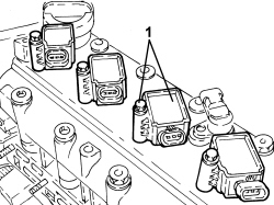  |
1. Undo the screws and remove the ignition coils. |
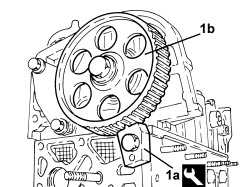  |
1. Fit the tool (1a) locking the camshaft driven pulley (1b).
|
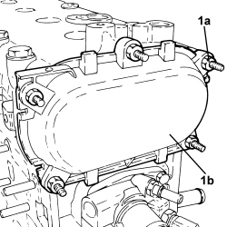  |
1. Undo the nuts (1a) and remove the cover (1b). |
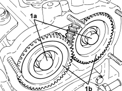  |
1. Loosen the screw (1a) securing the camshaft rear gears (1b). |
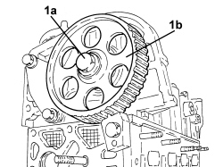  |
1. Undo the screw (1a) and remove the camshaft driven pulley (1b). |
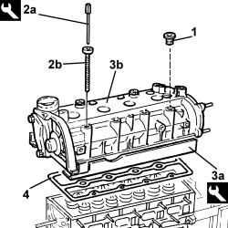  |
- Undo the screw and remove the camshaft driven pulley locking tool. 1. Undo the protective caps for the screws securing the camshaft housing to the cylinder head. 2. Using the tool (2a), undo the screws (2b) fixing the camshaft housing to the cylinder head.
3. Position the tool (3a) for retaining the tappets underneath the camshaft housing (3b) and remove it.
4. Remove the seal. |
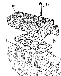  |
1. Undo the screws (1a), remove the cylinder head (1b) and keep the gasket (1c). 2. Remove the locating dowels. |
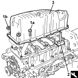  |
- Rotate the engine through 180° on the overhaul stand. 1. Undo the screws (1a) and the nuts (1b) securing the engine oil sump to the engine block. 2. Using the tool, cut the silicone sealant along the entire perimeter of the engine oil sump.
3. Remove the engine oil sump. |
|
|
- Thoroughly clean the contact surfaces between the engine block and the oil sump thoroughly. |