|
 Removing
(
Refitting Removing
(
Refitting )
)
- Open the fuse box cover in the engine compartment, remove fuse F22 (15A) and start the engine several times until the fuel pressure in the distribution manifold is expended. - Fit the fuse removed previously and close the fuse box casing. |

|
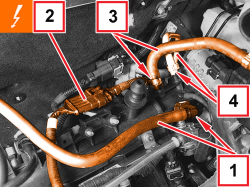
1. Disconnect the fuel return pipe rapid connector, pressure regulator side.
2. Disconnect the injector wiring coupling.
3. Loosen the band and disconnect the engine oil vapour inlet pipe.
4. Loosen the collar and disconnect the brake servo vacuum pipe.
|
|
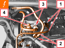
1. Disconnect the rapid connector for the fuel vapour supply pipe to the turbocharger inlet.
2. Disconnect the rapid connector for the fuel manifold supply pipe.
3. Disconnect the rapid connector for the fuel vapour supply pipe to the solenoid.
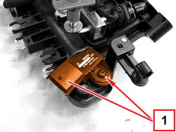
4. Disconnect the electrical connection for the air temperature/pressure sensor.
|
|
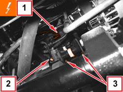
1. Detach the electrical connection for the fuel vapour recovery solenoid.
2. Open the engine wiring retaining clips.
3. Undo the lower bolts securing the air chamber.
|
|
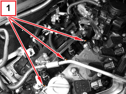
1. Undo the upper bolts securing the air chamber.
- Remove the air chamber assembly.
|
|
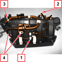
1. Open the fuel vapour pipe retaining clips.
2. Open the fuel pipe rapid connector retaining clips.
3. Loosen the band and disconnect the idle fuel vapour supply pipe.
4. Undo the bolts and remove the solenoid and single-acting valve assembly complete with pipes from the intake chamber.
|
|
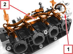
1. Disconnect the vacuum pipe for the fuel pressure regulator, air chamber side.
2. Undo the bolts and remove the fuel manifold complete with injectors and wiring.
|
|
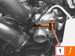
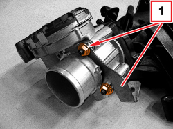
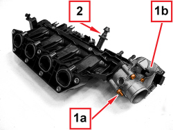
1. Undo the bolts (1a) and remove the throttle body (1b).
2. Remove the sound insulation cover centering pin.
|
|
|
Refitting
(
Removing
)
- Tighten the sound insulation cover centering pin. - Place the throttle body complete with a new gasket back in its housing and tighten the bolts. - Place the wiring holder bracket in position and tighten the nuts. - Refit the fuel manifold complete with injectors in its housing and tighten the bolts. - Connect the vacuum pipe for the fuel pressure regulator, air chamber side. - Position the air pressure/temperature sensor in its housing and tighten the bolt. - Place the solenoid and single-acting valve assembly in position complete with pipes attaching the retaining clips. - Tighten the bolts securing the fuel vapour solenoid to the air chamber and connect the electrical connection. - Connect the idle fuel vapour supply pipe and tighten the band. |
|
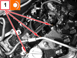
1. Position the air chamber complete with new gasket in its housing and tighten the upper new bolts to the recommended torque.
|
Air intake chamber |
Screw (to be replaced) |
M7 |
1.3 – 1.6 |
1.4 16v TJet 1.4 MultiAir 1.4 Turbo MultiAir |
|
|
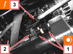
1. Tighten the lower new bolts securing the air chamber to the recommended torque.
|
Air intake chamber |
Screw (to be replaced) |
M7 |
1.3 – 1.6 |
1.4 16v TJet 1.4 MultiAir 1.4 Turbo MultiAir |
2. Close the engine wiring retaining clips.
3. Connect the electrical connection for the fuel vapour recovery solenoid valve.
|
|
|
- Connect the electrical connection for the air pressure/temperature sensor.
- Connect the rapid connector for the fuel vapour supply pipe to the solenoid.
- Connect the rapid connector for the fuel manifold supply pipe.
- Connect the rapid connector for the fuel vapour supply pipe to the turbocharger inlet.
- Attach the pipes and retaining clips to the bracket.
- Connect the brake servo vacuum pipe and tighten the band.
- Connect the engine oil vapour inlet pipe and tighten the band.
- Connect the injector wiring coupling.
- Connect the fuel return pipe rapid connector, pressure regulator side.
- Connect the electrical connection for the throttle body.
|
APPLIES TO VERSIONS WITH: GPL, Euro 5
APPLIES TO VERSIONS WITH: GPL, Euro 5
|
|
- Return the car to the workshop (in petrol operation mode).
- Place the car on a lift.
|
|
APPLIES TO VERSIONS WITH: GPL, Euro 5
|
|
- Open the fuse box cover in the engine compartment, remove fuse F22 (15 A) and start the engine several times until the fuel pressure in the distribution manifold is expended.
- Fit the fuse removed previously and close the fuse box casing.
|
|
APPLIES TO VERSIONS WITH: GPL, Euro 5
APPLIES TO VERSIONS WITH: GPL, Euro 5
APPLIES TO VERSIONS WITH: GPL, Euro 5
|
1. Disconnect the fuel return pipe rapid connector, pressure regulator side.
2. Disconnect the injector wiring coupling.
3. Loosen the band and disconnect the engine oil vapour inlet pipe.
4. Loosen the collar and disconnect the brake servo vacuum pipe.
|
|
APPLIES TO VERSIONS WITH: GPL, Euro 5
|
1. Disconnect the rapid connector for the fuel vapour supply pipe to the turbocharger inlet.
2. Disconnect the rapid connector for the fuel manifold supply pipe.
3. Disconnect the rapid connector for the fuel vapour supply pipe to the solenoid.
4. Disconnect the electrical connection for the air temperature/pressure sensor.
|
|
APPLIES TO VERSIONS WITH: GPL, Euro 5
APPLIES TO VERSIONS WITH: GPL, Euro 5
|
1. Detach the electrical connection for the fuel vapour recovery solenoid.
2. Open the engine wiring retaining clips.
3. Undo the lower bolts securing the air chamber.
|
|
APPLIES TO VERSIONS WITH: GPL, Euro 5
|
1. Undo the upper bolts securing the air chamber.
- Remove the air chamber assembly.
|
|
APPLIES TO VERSIONS WITH: GPL, Euro 5
|
1. Open the fuel vapour pipe retaining clips.
2. Open the fuel pipe rapid connector retaining clips.
3. Loosen the band and disconnect the idle fuel vapour supply pipe.
4. Undo the bolts and remove the solenoid and single-acting valve assembly complete with pipes from the intake chamber.
|
|
APPLIES TO VERSIONS WITH: GPL, Euro 5
APPLIES TO VERSIONS WITH: GPL, Euro 5
|
1. Disconnect the fuel pressure regulator vacuum pipe, air chamber side.
2. Undo the bolts and remove the fuel manifold complete with injectors and wiring.
|
|
APPLIES TO VERSIONS WITH: GPL, Euro 5
APPLIES TO VERSIONS WITH: GPL, Euro 5
|
1. Undo the screws (1a) and remove the throttle body (1b).
2. Remove the sound insulation cover centring pin.
|
|
APPLIES TO VERSIONS WITH: GPL, Euro 5
|
|
Refitting
(
Removing
)
- Tighten the sound insulation cover centring pin. - Place the throttle body complete with a new gasket back in its housing and tighten the bolts. - Fit the wiring mounting bracket in position and tighten the nuts. - Refit the fuel manifold complete with injectors in its housing and tighten the bolts. - Press-fit the vacuum pipe for the fuel pressure regulator, air chamber side. - Position the air pressure/temperature sensor in its housing and tighten the screw. - Place the solenoid and single-acting valve assembly in position complete with pipes attaching the retaining clips. - Tighten the bolts securing the fuel vapour solenoid to the air chamber and connect the electrical connection. - Connect the idle fuel vapour supply pipe and tighten the band. |
|
APPLIES TO VERSIONS WITH: GPL, Euro 5
|
1. Position the air chamber complete with new gasket in its housing and tighten the upper new bolts to the recommended torque.
|
Air intake chamber |
Screw (to be replaced) |
M7 |
1.3 – 1.6 |
1.4 16v TJet 1.4 MultiAir 1.4 Turbo MultiAir |
|
|
APPLIES TO VERSIONS WITH: GPL, Euro 5
|
1. Tighten the new lower air chamber fixing screws to the prescribed torque.
|
Air intake chamber |
Screw (to be replaced) |
M7 |
1.3 – 1.6 |
1.4 16v TJet 1.4 MultiAir 1.4 Turbo MultiAir |
2. Close the engine wiring retaining clips.
3. Connect the electrical connection for the fuel vapour recovery solenoid valve.
|
|
APPLIES TO VERSIONS WITH: GPL, Euro 5
|
|
- Connect the electrical connection for the air pressure/temperature sensor.
- Connect the rapid connector for the fuel vapour supply pipe to the solenoid.
- Connect the rapid connector for the fuel manifold supply pipe.
- Connect the rapid connector for the fuel vapour supply pipe to the turbocharger inlet.
- Engage the pipes with retaining clips in the bracket.
- Connect the brake servo vacuum pipe and tighten the band.
- Connect the engine oil vapour inlet pipe and tighten the band.
- Connect the injector wiring junction.
- Connect the fuel return pipe rapid connector, pressure regulator side.
- Connect the electrical connection for the throttle body.
|
|
APPLIES TO VERSIONS WITH: GPL, Euro 5