Connect the ammeter pliers N° 1806505000 to the diagnostic equipment using the EX01 cable.

|
There are two red LEDs on the handle of the pliers which light up when the ammeter pliers are open and warn the operator not to take any current measurements because they would be incorrect |
Position the pliers with the jaws closed and the red LEDs off, near the measurement point.
Zero the pliers using the "CALIBRATION" button.
|
|
On account of the extreme sensitivity of the equipment, it is normal for the reading to vary by several mA when the pliers are turned |
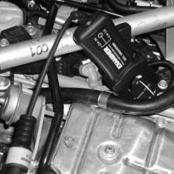
Position the wire connected to pin 3 of the ignition coil (primary winding control cable) so that it passes inside the ammeter plier jaws and, before taking any reading, make sure that the red LEDs on the pliers are off. Select "INSTRUMENT" on the diagnostic equipment and then "AMMETER".
Select 10 A PLIERS.
Select the time base at 1 sec.
Press the Start button and turn the ignition switch to the starting position
The diagram below shows normal coil primary winding current uptake with the engine warm and idling.
Repeat the same test, positioned on the wire connected to pin 3 of the other ignition coil, and check that a signal the same as the one shown below is present.
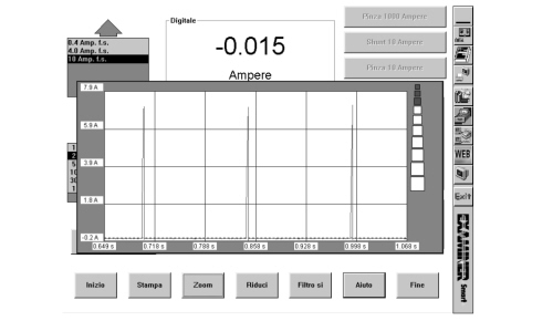
Ignition signal with normal pattern
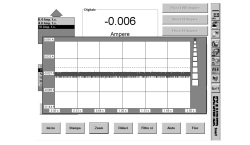
Interrupted or earthed ignition signal
If there are no ignition control signals to the coils, check the continuity and insulation to earth of the following cables:
- between the ignition coils and the engine control unit.