145 - MiTo   1.4 16v TJet   INSTRUMENT PANEL TRIM SUPPORTING CROSSMEMBER - R.R. WITH DASHBOARD REMOVED   7040A98   

Detail     Detail

Removing ( Refitting )

Keep the steering column adjustment lever closed during all the removing-refitting stages.

- Work on both sides.

   Op. 7040A65 CONSOLE SIDE CLOSING (ONE) - R.R.

   Op. 3380A44 HANDBRAKE/LINKAGE PROTECTION - R+R

   Op. 7040L22 REAR COVER ON TUNNEL - R.R.

   Op. 2125C02 GEAR CONTROL LEVER OUTER GAITER R R

   Op. 7040L20 TUNNEL COVER - R.R

   Op. 7210E36 R.R. FRONT SIDE DOOR


Enlarge the image


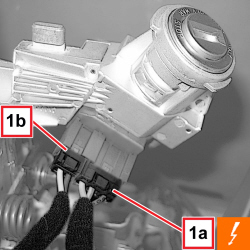
1. Detach the electrical connections (1a, 1b) for the ignition switch.


Description


Connector


1


IGNITION SWITCH


   See H001 IGNITION SWITCH


Enlarge the image


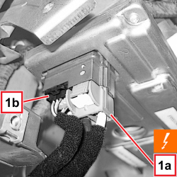
1. Disconnect the electrical connections (1a, 1b) for the electric steering control device.


Description


Connector


1


ELECTRIC STEERING CONTROL UNIT


   See M086 ELECTRIC STEERING CONTROL UNIT


Enlarge the image


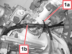
1. Open the band (1a) securing the wiring (1b) the electric steering device.


Enlarge the image


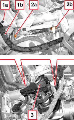
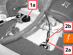
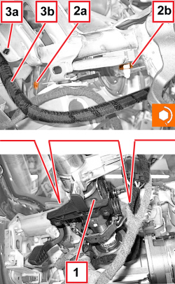
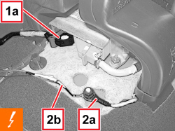
1. Working on the left side of the electric steering device, disconnect the retainer (1a) for the wiring (1b).

2. Working on both sides of the electric steering device, undo the bolts (2a) and the nuts (2b) securing the device to the crossmember.

3. Lower the electric steering device carefully onto the carpet.

Avoid the upper shaft for the electric steering device (3) slipping out of its housing at all costs after it has been disconnected from the dashboard supporting crossmember; secure it appropriately to lock it in position.


Enlarge the image


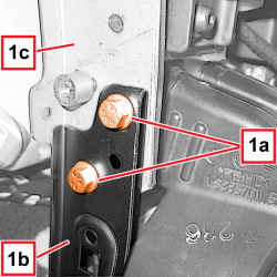
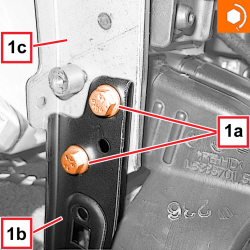
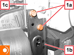
1. Working in the area of the tunnel, undo the bolts (1a) securing the left bracket (1b) to the dashboard supporting crossmember (1c).


Enlarge the image


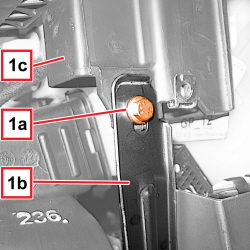
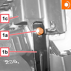
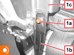
1. Undo the bolt (1a) securing the right bracket (1b) to the dashboard supporting crossmember (1c).


Enlarge the image


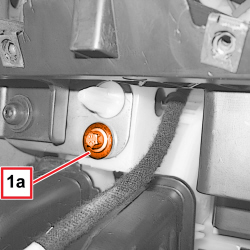
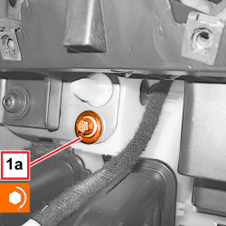
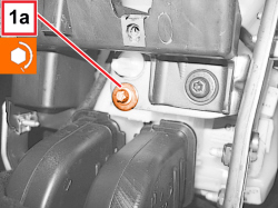
1. Working in the area of the tunnel, undo the bolt (1a) securing the crossmember to the air conditioning casing.


Enlarge the image


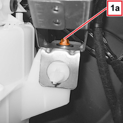
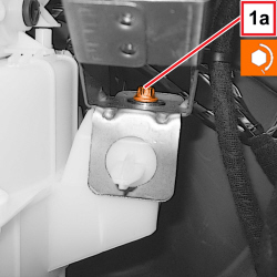
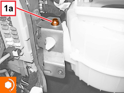
1. Undo the right bolt (1a) securing the crossmember to the air conditioning casing.


Enlarge the image


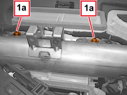
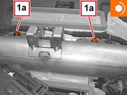
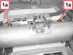
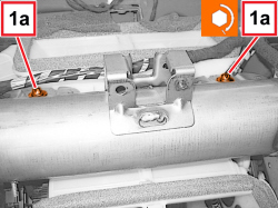
1. Undo the upper bolts (1a) securing the crossmember to the air conditioning casing.


Enlarge the image


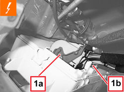
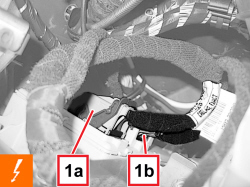
1. Working on the Air Bag control unit, disconnect the electrical connection (1a).


Description


Connector


1a


AIR BAG CONTROL UNIT


   See M060 AIR BAG CONTROL UNIT

2. Disconnect the earth leads (2a) and (2b).


Description


Connector


2


AIR BAG SYSTEM EARTH


   See C050 AIR BAG SYSTEM EARTH


Enlarge the image


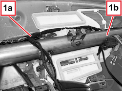
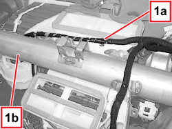
1. Disconnect all the retainers fastening the electrical wiring (1a) to the dashboard supporting crossmember (1b).


Enlarge the image


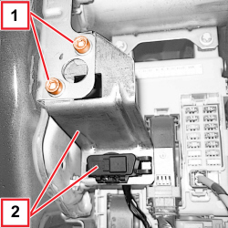
1. Working in the area of the body computer, undo the bolts.

2. Move the bracket and diagnostic socket.


Enlarge the image


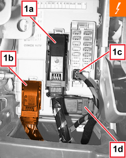
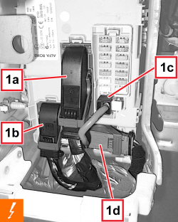
1. Detach the electrical connections (1a, 1b, 1c, 1d) from the body computer.


Description


Connector


1


BODY COMPUTER


   See M001 BODY COMPUTER


Enlarge the image


1. Detach the inner electrical connections (1a, 1b) for the body computer.


Description


Connector


1


BODY COMPUTER


   See M001 BODY COMPUTER


Enlarge the image


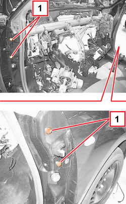
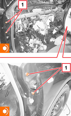
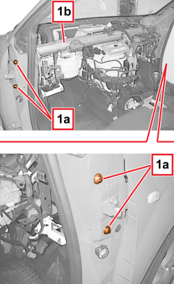
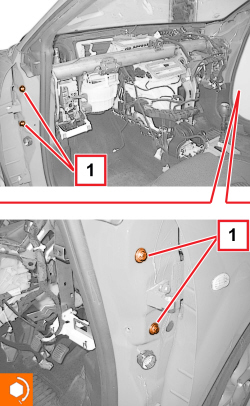
1. Working on both sides of the vehicle, undo the crossmember side fixing bolts and extract it.


Enlarge the image


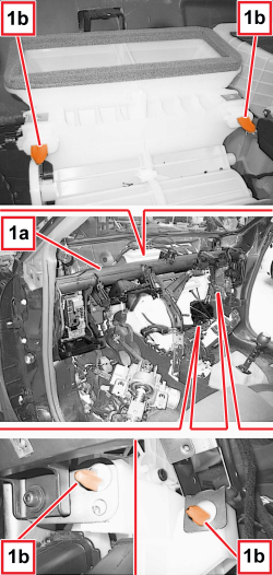
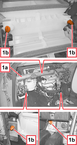
1. Remove the crossmember (1a) releasing it from the centering pins (1b) for the air conditioning casing.

- If necessary, strip the crossmember.

    Op. 7205A74 STRIPPING INSTRUMENT PANEL SUPPORTING CROSSMEMBER


Enlarge the image


Refitting ( Removing )

- Check that the dashboard support crossmember is not damaged.

- Reassemble the crossmember, if necessary.

   Op. 7205A74 STRIPPING INSTRUMENT PANEL SUPPORTING CROSSMEMBER

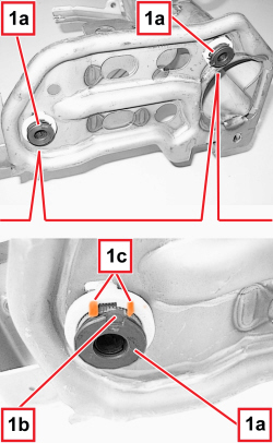
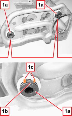
1. Working on both sides of the crossmember, fully tighten the crossmember centring bushes (1a) until the reference element (1b) fits into the seat (1c).

The operation described allows the bushes to be zeroed in order to permit the clearance take-up function whilst fastening the crossmember to the body using the side bolts.

- Replace the bushes, if necessary.


Enlarge the image


- Place the dashboard support crossmember in position and attach the centering pins for the air conditioning casing.

1. Tighten the side bolts fixing the crossmember; tighten them gradually and alternately (lower right and upper left and viceversa) to allow the side bushes to take up the clearances between the crossmember and bodyshell correctly.

Tighten the bolts to the specified torque.


Component


Fixing


dia


Value (daNm)


Validity


Under dashboard crossmember


Screw


M8


1.8 ÷ 2.2


Enlarge the image


- Connect the electrical connections to the Body Computer.

- Position the bracket and diagnostic socket and tighten the bolts.

- Connect all the retainers fastening the electrical wiring to the dashboard supporting crossmember.

- Connect the earth leads.

- Connect the electrical connection for the Air Bag control unit.

1. Screw in the upper bolts (1a) securing the crossmember to the air conditioning casing, then tighten them to the recommended torque.


Component


Fixing


dia


Value (daNm)


Validity


Air conditioning casing


Screw


M6


0.5 ÷ 0.7


Enlarge the image


1. Screw in the right bolt (1a) securing the crossmember to the air conditioning casing, then tighten it to the recommended torque.


Component


Fixing


dia


Value (daNm)


Validity


Air conditioning casing


Screw


M6


0.5 ÷ 0.7


Enlarge the image


1. Screw in the bolt (1a) in the area of the tunnel securing the crossmember to the air conditioning casing, then tighten it to the recommended torque.


Component


Fixing


dia


Value (daNm)


Validity


Air conditioning casing


Screw


M6


0.5 ÷ 0.7


Enlarge the image


1. Screw in the bolt (1a) securing the right bracket (1b) to the dashboard supporting crossmember (1c), then tighten it to the recommended torque.


Component


Fixing


dia


Value (daNm)


Validity


Bracket connecting crossmember to tunnel


Screw


M8


0.6 ÷ 1.0


Enlarge the image


1. Screw in the bolts (1a) securing the left bracket (1b) to the dashboard supporting crossmember (1c), then tighten them to the recommended torque.


Enlarge the image


1. Raise the electric steering device and position it.

2. Working on both sides of the electric steering device, screw in the bolts (2a) and the nuts (2b) securing the device to the crossmember, the tighten them to the recommended torque.


Component


Fixing


dia


Value (daNm)


Validity


Steering column to under dashboard crossmember


Screw


M8


1.6 ÷ 2.4


Component


Fixing


dia


Value (daNm)


Validity


Steering column to under dashboard crossmember


Nut


M8


1.6 ÷ 2.4


3. Working on the left side of the electric steering device, connect the retainer (3a) for the wiring (3b).

- Fasten the wiring to the electric steering device using the retaining band.

- Connect the electrical connections for the electric steering control device.

- Connect the electrical connections for the ignition switch.

    Op. 7210E36 R.R. FRONT SIDE DOOR

    Op. 7040L20 TUNNEL COVER - R.R

    Op. 2125C02 GEAR CONTROL LEVER OUTER GAITER R R

    Op. 7040L22 REAR COVER ON TUNNEL - R.R.

    Op. 3380A44 HANDBRAKE/LINKAGE PROTECTION - R+R

    Op. 7040A65 CONSOLE SIDE CLOSING (ONE) - R.R.

APPLIES TO VERSIONS WITH: Right-hand drive

Removing ( Refitting )

Keep the steering column adjustment lever closed during all the removing-refitting stages.

- Work on both sides.

   Op. 7040A65 CONSOLE SIDE CLOSING (ONE) - R.R.

   Op. 3380A44 HANDBRAKE/LINKAGE PROTECTION - R+R

   Op. 7040L22 REAR COVER ON TUNNEL - R.R.

   Op. 2125C02 GEAR CONTROL LEVER OUTER GAITER R R

   Op. 7040L20 TUNNEL COVER - R.R

   Op. 7210E36 R.R. FRONT SIDE DOOR

   Op. 7040A24 DASHBOARD CLOSURE LOWER TRIM - R.R.

   Op. 5580E08 AERIAL FOR ELECTRONIC KEY (CODE) - R.R.

   Op. 4110D20 STEERING ELECTRICAL CONTROL DEVICE - R R

APPLIES TO VERSIONS WITH: Right-hand drive


Enlarge the image


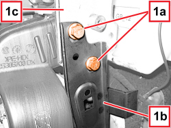
1. Working in the area of the tunnel, undo the screws (1a) fixing the right bracket (1b) to the dashboard supporting crossmember (1c).

APPLIES TO VERSIONS WITH: Right-hand drive


Enlarge the image


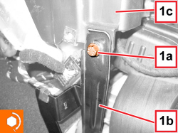
1. Undo the screw (1a) fixing the left bracket (1b) to the dashboard supporting crossmember (1c).

APPLIES TO VERSIONS WITH: Right-hand drive


Enlarge the image


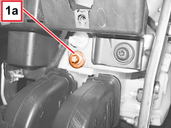
1. Working in the area of the tunnel, undo the bolt (1a) securing the crossmember to the air conditioning casing.

APPLIES TO VERSIONS WITH: Right-hand drive


Enlarge the image


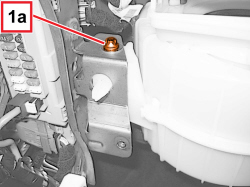
1. Undo the left screw (1a) fixing the air conditioning casing to the crossmember.

APPLIES TO VERSIONS WITH: Right-hand drive


Enlarge the image


1. Undo the upper bolts (1a) securing the crossmember to the air conditioning casing.

APPLIES TO VERSIONS WITH: Right-hand drive


Enlarge the image


1. Working on the Air Bag control unit, disconnect the electrical connection (1a).


Description


Connector


1a


AIR BAG CONTROL UNIT


   See M060 AIR BAG CONTROL UNIT

2. Disconnect the earth leads (2a) and (2b).


Description


Connector


2


AIR BAG SYSTEM EARTH


   See C050 AIR BAG SYSTEM EARTH

APPLIES TO VERSIONS WITH: Right-hand drive


Enlarge the image


1. Disconnect all the retainers fastening the electrical wiring (1a) to the dashboard supporting crossmember (1b).

APPLIES TO VERSIONS WITH: Right-hand drive


Enlarge the image


1. Detach the electrical connections (1a, 1b, 1c, 1d) from the body computer.


Description


Connector


1


BODY COMPUTER


   See M001 BODY COMPUTER

APPLIES TO VERSIONS WITH: Right-hand drive


Enlarge the image


1. Detach the inner electrical connections (1a, 1b) for the body computer.


Description


Connector


1


BODY COMPUTER


   See M001 BODY COMPUTER

APPLIES TO VERSIONS WITH: Right-hand drive


Enlarge the image


1. Working on both sides of the vehicle, undo and extract the side screws (1a) fixing the dashboard supporting crossmember (1b).

APPLIES TO VERSIONS WITH: Right-hand drive


Enlarge the image


1. Remove the dashboard supporting crossmember (1a) releasing it from the locating pins (1b) for the air conditioning casing.

APPLIES TO VERSIONS WITH: Right-hand drive

- If necessary, disassemble the crossmember.

    Op. 7205A74 STRIPPING INSTRUMENT PANEL SUPPORTING CROSSMEMBER

APPLIES TO VERSIONS WITH: Right-hand drive


Enlarge the image


Refitting ( Removing )

- Check that the dashboard supporting crossmember is not damaged.

   Op. 7205A74 STRIPPING INSTRUMENT PANEL SUPPORTING CROSSMEMBER

1. Working on both sides of the dashboard supporting crossmember, fully tighten the crossmember centring bushes (1a) until the reference element (1b) engages with the housing (1c).

The operation described allows the bushes to be zeroed in order to permit the clearance take-up function whilst fastening the crossmember to the body using the side bolts.

- Replace the bushes, if necessary.

APPLIES TO VERSIONS WITH: Right-hand drive


Enlarge the image


- Place the dashboard support crossmember in position and attach the centering pins for the air conditioning casing.

1. Tighten the side screws fixing the dashboard supporting crossmember; tighten them gradually and alternately (lower right and upper left and viceversa) to allow the side bushes to recover the clearances between the crossmember and body correctly.

Tighten the bolts to the specified torque.


Component


Fixing


dia


Value (daNm)


Validity


Under dashboard crossmember


Screw


M8


1.8 ÷ 2.2


APPLIES TO VERSIONS WITH: Right-hand drive

- Connect the electrical connections for the Body Computer.

- Connect all the retainers fastening the electrical wiring to the dashboard supporting crossmember.

- Connect the earth leads.

- Connect the electrical connection for the Air Bag control unit.

APPLIES TO VERSIONS WITH: Right-hand drive


Enlarge the image


1. Screw in the upper bolts (1a) securing the crossmember to the air conditioning casing, then tighten them to the recommended torque.


Component


Fixing


dia


Value (daNm)


Validity


Air conditioning casing


Screw


M6


0.5 ÷ 0.7


APPLIES TO VERSIONS WITH: Right-hand drive


Enlarge the image


1. Insert the left screw (1a) fixing the air conditioning casing to the crossmember, then tighten it to the prescribed torque.


Component


Fixing


dia


Value (daNm)


Validity


Air conditioning casing


Screw


M6


0.5 ÷ 0.7


APPLIES TO VERSIONS WITH: Right-hand drive


Enlarge the image


1. Screw in the bolt (1a) in the area of the tunnel securing the crossmember to the air conditioning casing, then tighten it to the recommended torque.


Component


Fixing


dia


Value (daNm)


Validity


Air conditioning casing


Screw


M6


0.5 ÷ 0.7


APPLIES TO VERSIONS WITH: Right-hand drive


Enlarge the image


1. Tighten the screw (1a) fixing the left bracket (1b) to the dashboard supporting crossmember (1c), then tighten it to the prescribed torque.


Component


Fixing


dia


Value (daNm)


Validity


Bracket connecting crossmember to tunnel


Screw


M8


0.6 ÷ 1.0


APPLIES TO VERSIONS WITH: Right-hand drive


Enlarge the image


1. Tighten the screws (1a) fixing the right bracket (1b) to the dashboard supporting crossmember (1c), then tighten them to the prescribed torque.


Component


Fixing


dia


Value (daNm)


Validity


Bracket connecting crossmember to tunnel


Screw


M8


0.6 ÷ 1.0


APPLIES TO VERSIONS WITH: Right-hand drive

    Op. 4110D20 STEERING ELECTRICAL CONTROL DEVICE - R R

    Op. 5580E08 AERIAL FOR ELECTRONIC KEY (CODE) - R.R.

    Op. 7040A24 DASHBOARD CLOSURE LOWER TRIM - R.R.

    Op. 7210E36 R.R. FRONT SIDE DOOR

    Op. 7040L20 TUNNEL COVER - R.R

    Op. 2125C02 GEAR CONTROL LEVER OUTER GAITER R R

    Op. 7040L22 REAR COVER ON TUNNEL - R.R.

    Op. 3380A44 HANDBRAKE/LINKAGE PROTECTION - R+R

    Op. 7040A65 CONSOLE SIDE CLOSING (ONE) - R.R.