
 Removing
(
Refitting
Removing
(
Refitting )
)
- Remove the front seats.
|
|
Removing
(
Refitting
)
- Remove the front seats. |
|
|
|
|
|
Op. 7040H66 LEFT REAR SIDE TRIM, WITH REAR PARCEL SHELF SUPPORT - R.R. |
|
Op. 7040H67 RIGHT REAR SIDE TRIM, WITH REAR PARCEL SHELF SUPPORT - R.R. |
|
- Work on both sides. Op. 7040H38 CENTRE PILLAR UPPER ELEMENT (ONE), LEFT OR RIGHT - R.R |
|
|
|
|
|
- Remove all the handles. Op. 7065C28 GRAB HANDLE ON ROOF LINING (ONE), LH OR RH - R.R. |
|
|
Op. 7040H16 ROOF PANEL LINING FOR VERSIONS WITH SUN ROOF - R.R |
|
|
- Remove the side guides. |
|
Op. 7030B26 SLIDING ROOF BLIND - R+R WITH ROOF PANEL REMOVED |
|
|
|
Op. 7030B51 SLIDING ROOF CENTRAL ANTI-WIND NOISE GASKET - R R |
|
|
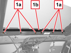  |
1. Undo the screws (1a) and remove the sunroof blind attachment trim (1b). |
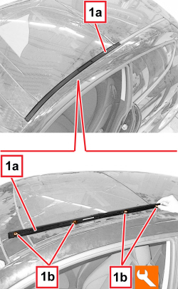  |
1. Working on both sides of the vehicle, gradually lift the front side mouldings (1a) and release the inner retainers (1b) with the special tool.
|
|
|
|
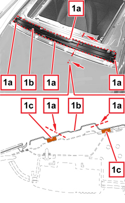  |
- Protect the vehicle fittings with suitable cloths. 1. With a saw, make cuts (1a) and remove the front section of the sliding roof frame (1b) (this is necessary to facilitate the subsequent cutting of the sealant strips (1c) fixing the front section of the sliding roof frame to the body).
|
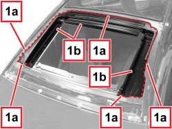  |
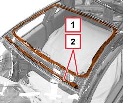
1. With a saw, make cuts (1a) and remove the sliding roof frame (1b) (this is necessary to facilitate the subsequent cutting of the side and rear sealant strips fixing the sliding roof frame to the body).
|
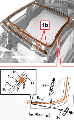  |
- The sliding roof sealant strips can be cut using piano wire or a vibrating knife; both methods are described below. - To cut using piano wire, proceed as described below.
1. Cut a length of piano wire of about 50 cm, then use pliers to introduce one end (1a) of the wire through the sealant bead (1b) securing the sliding roof frame (1c) to the body. 2. Fasten one end (1a) of the wire to the special retaining tool (2a) located inside the vehicle. Fasten one end (2b) of the wire to the traction handle (2c) located outside the vehicle. 3. The operator inside the vehicle should keep the end of the tool (2a) on the strip of sealant (1b) about 30 cm away from the point where the wire passes through, whilst the other operator, outside the vehicle, should pull the handle (2c), following the profile of the sliding roof frame, and cut the sealant bead (1b). Repeat the operation in sections of about 30 cm until the bead of sealant (3a) is completely cut. - Remove the sliding roof frame. |
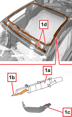  |
- To cut using a vibrating knife, proceed as described below.
1. Use the vibrating knife (1a) with blade (1b) or (1c) and cut the sealant beads (1d). - Remove the sliding roof frame. |
  |
Refitting
(
Removing
)
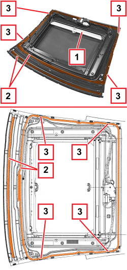
1. Using suitable equipment, cut and level the beads of sealant in the sliding roof housing leaving a thickness of between 0.25 and 1 mm, taking care not to scratch the paintwork. The thickness of the sealant remaining in the housing will act as a support for the new bonding. 2. Thoroughly clean the sun roof housing using an air jet and degrease fully using heptane. When bonding more than 60 minutes after the sealant bead has been cut and levelled, the surface of the sealant itself must be treated using the special activating product and it is necessary to wait for 15 minutes before fixing the windscreen.
- If necessary, touch up the paintwork. |
  |
1. Open the new sliding roof blind. 2. Degrease the adhesive surface of the new sun roof using heptane. 3. Check that the shims are fitted. |
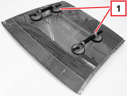  |
1. Apply two suction pads on the outer sides of the sliding roof, as shown in the picture. |
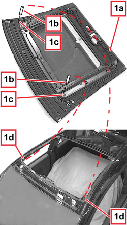  |
1. With the help of one operator outside the vehicle and another operator inside, test fit the sliding roof (1a). If necessary, screw the locating pins (1c) into the sliding roof housings (1d) to facilitate the centring of the sliding roof in the housings (1d) when moving it close to the body. |
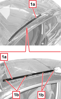  |
1. Working on both sides of the vehicle, temporarily place the front side mouldings (1a) in position and engage the inner retainers (1b) |
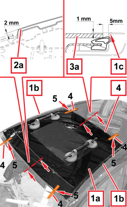  |
1. Centre the sliding roof (1a) on the side section irons (1b) of the body; in addition position it with the the clear section 5 mm away from the rear section iron (1c) of the body, as shown in the picture. 2. Check that the front end (2a) of the front section of the sliding roof is about 2 mm higher than the windscreen, as shown in the picture. 3. Check that the rear end (3a) of the sliding roof is about 1 mm lower than the sheet metal roof, as shown in the picture. 4. When the sun roof has been centred, mark the position of the sun roof in relation to the housing using strips of adhesive tape. 5. Cut the adhesive tape strips. - Working on both sides of the vehicle, gradually lift the front side mouldings and release the inner retainers with the special tool.
- Remove the sliding roof. |
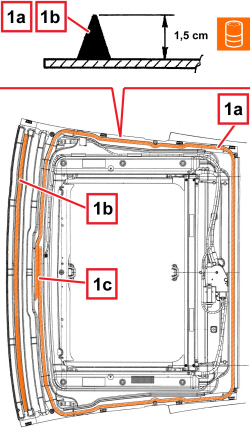  |
1. Using an air gun, apply a bead of sealant (1a) along the perimeter of the sliding roof and the front channel (1b) as evenly as possible.
|
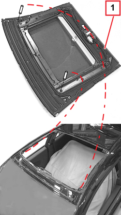  |
1. With the help of one operator outside the vehicle and another one inside and following the instructions for the previous test fitting, place the sliding roof in position immediately after applying the sealant then let it bed in. |
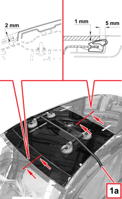  |
1. Position the belt (1a) as illustrated and tension it to exert even pressure on the sliding roof, to guarantee that the sliding roof frame and the frame housing are correctly connected. Check that measurements shown in the picture are reached. |
  |
- Before refitting the vehicle's interior and exterior elements, check that there are no infiltration points by carrying out a water leakage test.
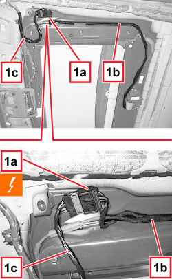
1. Connect the electrical connection (1a) for the sliding roof wiring (1b) to the vehicle compartment wiring (1c).
|
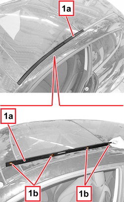  |
1. Working on both sides of the vehicle, place the front side mouldings (1a) in position and engage the inner retainers (1b) |
|
|
- If necessary, temporarily connect the sliding roof switch unit and test the operation of the new sliding roof. Op. 7040H16 ROOF PANEL LINING FOR VERSIONS WITH SUN ROOF - R.R |
|
|
Op. 7065C28 GRAB HANDLE ON ROOF LINING (ONE), LH OR RH - R.R. |
|
|
|
|
|
Op. 7040H38 CENTRE PILLAR UPPER ELEMENT (ONE), LEFT OR RIGHT - R.R |
|
Op. 7040H67 RIGHT REAR SIDE TRIM, WITH REAR PARCEL SHELF SUPPORT - R.R. |
|
Op. 7040H66 LEFT REAR SIDE TRIM, WITH REAR PARCEL SHELF SUPPORT - R.R. |
|
|
|
|
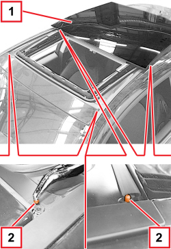  |
1. Open the sliding roof to the end of travel. 2. Remove and discard the four sliding roof positioning shims (red) with pliers. |
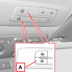  |
1. After the battery has been disconnected or a fuse has blown or the motor has been removed, the operation of the sliding roof must be initialised again. - Proceed as follows: - press the closing button until the roof is completely closed. - release the button. - press close button and keep it pressed for at least 10 seconds and/or until the glass panel clicks forwards. - now, release the button. - press the button (A) within 5 seconds of the previous action and keep it pressed: the glass panel will complete a full opening and closing cycle. - only release the button at the end of this cycle. |

