
 Removing
(
Refitting
Removing
(
Refitting )
)
- Place the car on a lift.
|
|
Removing
(
Refitting
)
- Place the car on a lift. |
|
|
|
|
Op. 4410D17 REINFORCEMENT FOR FRONT SUSPENSION CROSSMEMBER - R.R. |
|
Op. 1076B72 INTERMEDIATE EXHAUST PIPE WITH HOSE SECTION - R+R |
|
|
Op. 5540C42 SENSOR FOR CORRECTING/ALIGNING GAS DISCHARGE LIGHT CLUSTERS ON FRONT SUSPENSION - R.R. |
|
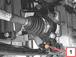  |
1. Undo the bolt securing the left wishbone to the wheel steering knuckle. |
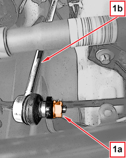  |
1. Undo the nut (1a) and disconnect the joint (1b) from the anti-roll bar. |
|
|
- Repeat the same operations on the right side. |
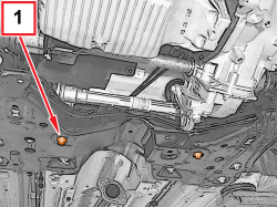  |
1. Undo the bolts fixing the steering box to the front suspension crossmember. |
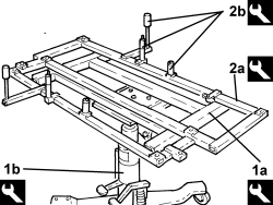  |
1. Fit the support (1a) on the column lift (1b).
2. Fit the frame (2a) complete with adaptors (2b).
|
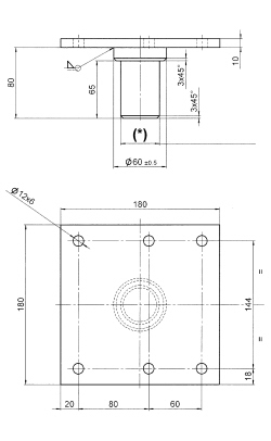  |
- If the above hydraulic lift is not available, use a general hydraulic lift plus the adaptor shown in the drawing, which must be made up by the workshop to allow the use of the above frames. |
|
|
(*): Adjust the diameter of the adaptor shank according to the hydraulic lift used. |
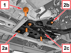  |
1. Support the front suspension crossmember using the tool prepared previously, taking care that the adaptors are positioned in the centering openings as illustrated. 2. Undo the screws (2a), (2b) and remove the suspension crossmember (2c). |
  |
Refitting
(
Removing
)
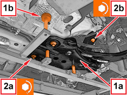
1. Place the suspension crossmember (1a) in position taking care that the adaptors (1b) are positioned in the centering openings in the body. 2. Tighten the new screws (2a) and (2b) securing the suspension crossmember to the body to the prescribed torque.
|
|
|
- Remove the equipment used for supporting the suspension crossmember. |
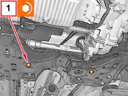  |
1. Tighten the bolts fixing the steering box to the front suspension crossmember to the prescribed torque.
|
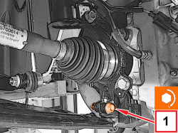  |
1. Connect the left wishbone to the wheel steering knuckle and tighten the new bolt to the prescribed torque.
|
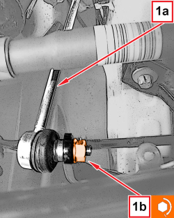  |
1. Connect the joint (1a) to the anti-roll bar and tighten the new nut (1b) to the prescribed torque.
|
|
|
- Repeat the same operations on the right side. |
|
|
Op. 5540C42 SENSOR FOR CORRECTING/ALIGNING GAS DISCHARGE LIGHT CLUSTERS ON FRONT SUSPENSION - R.R. |
|
|
Op. 1076B72 INTERMEDIATE EXHAUST PIPE WITH HOSE SECTION - R+R |
|
Op. 4410D17 REINFORCEMENT FOR FRONT SUSPENSION CROSSMEMBER - R.R. |
|
|
|
|
|
- Remove the car from the lift. Op. 4450A10 FRONT WHEEL GEOMETRY - CHECK USING OPTICAL EQUIPMENT - INCLUDES ADJUSTMENT IF NECESSARY |
|