
 Removing
(
Refitting
Removing
(
Refitting )
)
The procedure below concerns the 120 HP version.
|
|
Removing
(
Refitting
)
The procedure below concerns the 120 HP version. |
|
|
|
|
|
- Place the vehicle on a lift. |
|
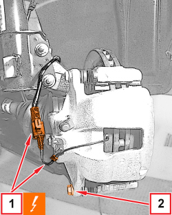  |
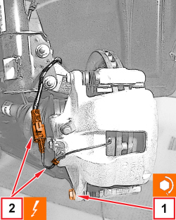
1. Disconnect the electrical connector of the pad wear sensor and release the wiring of the intermediate clip.
2. Undo the lower screw fixing the front brake caliper to the bracket. |
|
|
- Rotate the front brake caliper and link it suitably as shown in the figure. - Remove all traces of any residual adhesive on the side tabs and on the caliper piston.
|
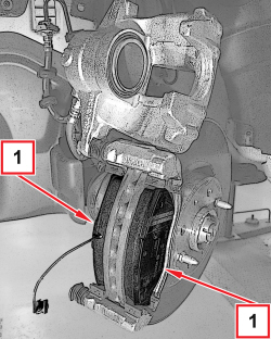  |
1. Remove the front brake pads from the bracket. |
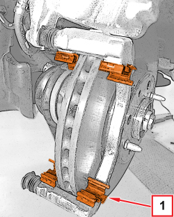  |
1. Remove the pad sliding clips from the brake caliper bracket. |
|
|
Refitting
(
Removing
)
- Clean the clip housings on the bracket.
- Place the new sliding clips from the brake pad kit in their seats in the bracket. |
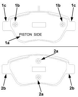  |
- Place the front brake pads in their housings according to the following instructions: 1. the piston side pad (inside of the vehicle) has the words "PISTON SIDE" (1a) and the rivets (1b) should be parallel to the fixing tabs (1c). 2. the vehicle outer pad can be identified through the rivets (2a) perpendicular to the fixing tabs (2b). - Remove any protection and double sided film from the back of the pad. |
  |
1. Fit the front brake caliper in position and tighten a new lower screw to the prescribed torque.
2. Connect the electrical connector of the pad wear sensor and engage the wiring of the intermediate clip.
|
|
|
|
- Remove the vehicle from the lift. |
|
|
Removing
(
Refitting
)
The procedure below concerns the 155 HP version. |
|
|
- Place the vehicle on a lift. |
|
|
- Check the brake fluid level as piston retraction described here below increase brake fluid level in the reservoir. Make sure the fluid level does not cause its leak. |
|
|
|
|
|
|
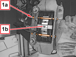  |
1. Take out the pins (1a) and remove the retaining spring (1b). |
|
|
- Slightly move the pistons apart with a divider or other suitable tool by pressing on the pads to be removed. Piston retraction must be made so that worn pads can be removed and new ones can be refitted. |
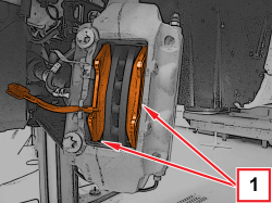  |
1. Remove the front brake pads. |
|
|
Refitting
(
Removing
)
- Clean the brake pad resting zone using suitable materials and products (e.g. a moist cloth).
- The new brake pads available as Spare parts include sound-deadening stainless steel plates to be installed individually according to the instructions below. |
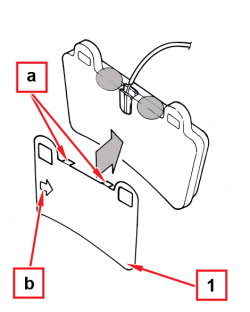  |
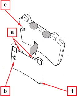
Inner left pad with wear sensor 1. Correctly place the new stainless steel plate on the pad back. The plate is correctly placed when the two tabs (a) firmly rest on the upper edge of the pad back and the arrow (b) printed on it is directed towards the standard disc direction of rotation. |
  |
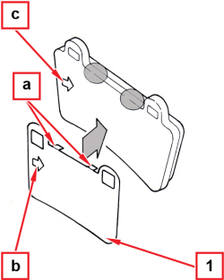
Right inner pad and left outer pad 1. Correctly place the new stainless steel plates on the pad back. The plates are correctly placed when the two tabs (a) firmly rest on the upper edge of the pad back and the arrow (b) printed on them is directed towards the standard disc direction of rotation, like the arrow (c) printed on the pads. |
  |
Right outer pad 1. Correctly place the new stainless steel plate on the pad back. The plate is correctly placed when the two tabs (a) firmly rest on the upper edge of the pad back and the arrow (b) printed on it is directed towards the standard disc direction of rotation, like the arrow (c) printed on the pad. |
|
|
- Fit the new pads by correctly locating them in their housings, paying attention to the arrows printed on the stainless steel plates.
|
|
|
- Arrange the retaining spring of the brake pads in its housing and fasten it with the corresponding pins. - Connect the electric connection of the brake pad wear wire and engage the wiring in its housing on the caliper. |
|
|
|
|
|
- Check the brake fluid level in the reservoir. - Press the brake pedal to restore force and normal operation of the pedal itself. - Remove the vehicle from the lift. |

