145 - MiTo   1.4 16v TJet   POWERTRAIN ASSEMBLY (MANUAL TRANSMISSION), REMOVED - SEPARATE AND REASSEMBLE   1004D10   

Detail     Detail


Enlarge the image


Removing ( Refitting )

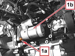
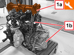
1. With the tool (1a) support the power unit (1b) as shown in the figure.


Tool


Name


Function


Validity


1871001700


Balance


Removing/refitting power unit


Enlarge the image


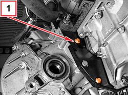
1. Undo the screw fixing the engine flywheel guard to the gearbox.

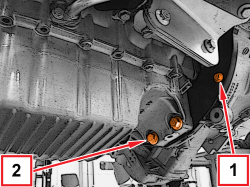
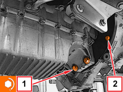
2. Undo the screws fixing the gearbox to the engine oil sump.


Enlarge the image


1. Undo the screws fixing the engine flywheel guard to the gearbox.


Enlarge the image


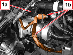
1. Open the protective cover (1a), loosen the nut and remove the starter wiring (1b).


Enlarge the image


1. Undo the upper screw securing the starter to the gearbox.


Enlarge the image


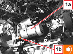
1. Undo the lower screw (1a) and remove the starter (1b).


Enlarge the image


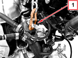
1. Disconnect the power unit lifting points, gearbox side and connect the engine in the point shown in the figure.


Enlarge the image


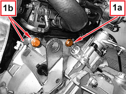
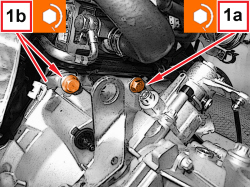
1. Undo the upper screws (1a) and (1b) fixing the gearbox to the engine.


Enlarge the image


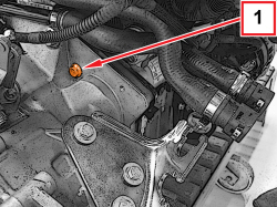
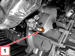
1. Undo the side screw fixing the gearbox to the engine.


Enlarge the image


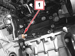
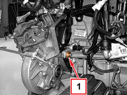
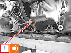
1. Undo the nut fixing the gearbox to the engine.


Enlarge the image


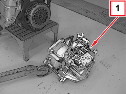
1. Separate the gearbox from the power unit.


Enlarge the image


Refitting ( Removing )

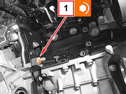
1. Fit in its housing and tighten the nut securing it to the engine to the prescribed torque.


Component


Fastening


Ø


Value (daNm)


Validity


Manual gearbox to engine


Nut


M12


4.8 – 7.2


1.4 8v

1.4 16v TJet

1.4 16v

1.6 JTD 16v

1.4 MultiAir

1.4 Turbo MultiAir

1.3 Multijet 85/95 HP

0.9 TwinAir


Enlarge the image


1. Place the air delivery pipe supporting bracket in its housing on the intake chamber and tighten to the prescribed torque the side screw fixing the gearbox to the engine.


Component


Fastening


Ø


Value (daNm)


Validity


Manual gearbox to engine


Screw


M12


4.8 – 7.2


Enlarge the image


1. Place the wiring mounting bracket in its seat and tighten the upper screws (1a) and (1a) fixing the gearbox to the engine to the prescribed torque.


Component


Fastening


Ø


Value (daNm)


Validity


Manual gearbox to engine


Screw


M12


4.8 – 7.2


Enlarge the image


1. Place the starter (1a) in its housing and tighten the gearbox fixing screws (1b) to the prescribed torque.


Component


Fastening


Ø


Value (daNm)


Validity


Starter motor


Screw


M8


2.25 – 2.75


- Place the starter wiring in its seat, tighten the nut and close the protective cover.

- Tighten the screws fixing the engine flywheel guard to the gearbox.


Enlarge the image


1. Tighten the screws fixing the gearbox to the engine sump to the prescribed torque.


Component


Fastening


Ø


Value (daNm)


Validity


Manual gearbox to engine


Screw


M10


3.6 – 4.4


2. Tighten the screw fixing the engine flywheel guard to the gearbox.


Enlarge the image


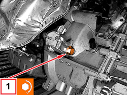
1. Undo the nut fixing the gearbox to the engine, intake side.

- Remove the gearbox from the engine.


Enlarge the image


1. Tighten the screw fixing the gearbox to the engine oil sump to the prescribed torque, intake side.


Component


Fastening


Ø


Value (daNm)


Validity


Manual gearbox to engine


Screw


M10


3.6 – 4.4