
 Removing
(
Refitting
Removing
(
Refitting )
)
- Position the vehicle on a lift.
|
|
Removing
(
Refitting
)
- Position the vehicle on a lift. |
|
|
|
|
Op. 7055B65 ENGINE COMPARTMENT DUST COVER IN LEFT FRONT WHEEL ARCH - R.R. |
|
|
|
|
|
Op. 0010T84 AIR CONDITIONING SYSTEM REFRIGERANT - DEHYDRATING AND REPRESSURIZING |
|
|
|
|
|
|
|
Op. 5050A12 WINDSCREEN WASHER FLUID RESERVOIR FILLER PIPE (IN ENGINE COMPARTMENT) - R.R. |
|
|
Op. 1048B25 INTERMEDIATE RIGID PIPE BETWEEN HEAT EXCHANGER AND THROTTLE BODY - R R |
|
Op. 1048B30 AIR SUPPLY HOSE FROM RIGID PIPE TO THROTTLE BODY - REPLACE |
|
|
|
|
|
Op. 1048A50 LOWER ENGINE BLOCK - R.R. CLEAN SEALING SURFACES AND APPLY SEALANT |
|
Op. 4410D17 REINFORCEMENT FOR FRONT SUSPENSION CROSSMEMBER - R.R. |
|
Op. 1076B72 INTERMEDIATE EXHAUST PIPE WITH HOSE SECTION - R+R |
|
|
Op. 1008C34 BRACKET ON GEARBOX FOR LOWER REACTION ROD - R.R. |
|
Op. 2710A14 RIGHT DRIVESHAFT WITH JOINTS AND INTERMEDIATE DRIVESHAFT - R+R |
|
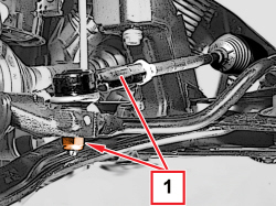  |
1. Undo the nut fixing the steering rod to the wheel strut. |
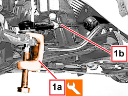  |
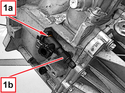
1. Using the tool (1a), disconnect the steering rod (1b) from the wheel strut.
|
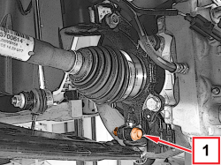  |
1. Undo the bolt securing the front suspension wishbone to the wheel strut. |
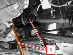  |
1. With a suitable tool, remove the left driveshaft from the differential and link it on the side. |
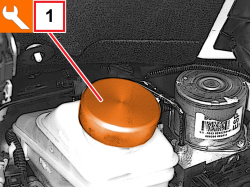  |
1. Unscrew the brake-clutch fluid reservoir plug and fit the tool.
|
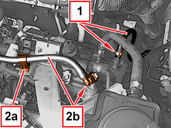  |
1. Loosen the band and disconnect the brake servo vacuum pipe from the intake chamber. 2. Open the clip (2a) and disconnect the quick connector of the fuel return pipe to the tank (2b), on pressure regulator side. |
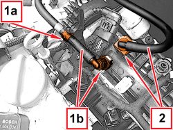  |
1. Open the clip (1a) and disconnect the quick connector of the fuel delivery pipe (1b), on fuel manifold pipe side. 2. Disconnect the fuel vapour pipe quick coupling, intake chamber side. |
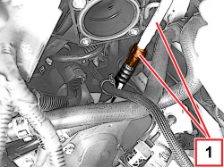  |
1. Disconnect the coolant pipe quick connector. |
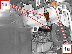  |
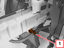
1. Open the clip (1a) and disconnect the quick intermediate connector of the coolant pipe (1b). |
  |
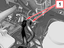
1. Open the coolant fluid pipe retaining clip on the side panel. |
  |
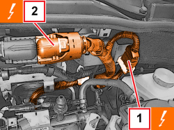
1. Disconnect the quick connectors for the coolant supply and return pipes, heater side. |
  |
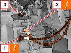
1. Disconnect the engine intermediate coupling.
2. Disconnect the electrical connection for the engine management control unit.
|
  |
1. Disconnect the electrical connection for the reversing light switch.
2. Undo the screw and disconnect the battery earth lead.
3. Move the clip back and disconnect the hose from the clutch release coaxial actuator. |
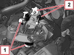  |
1. Disconnect the gear engagement/selector cables. 2. Open the clips and release the gear selector and engagement cables from the reaction bracket. |
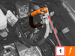  |
1. Undo the nut and disconnect the starter supply lead.
|
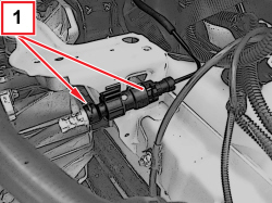  |
1. Retract the clip and remove the additional vibration damper with relevant hose. |
  |
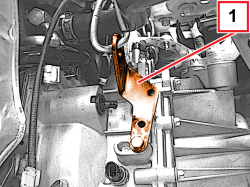
1. Lift the clip (1a) and remove the three-way connector (1b). |
  |
1. Fit the bracket for power unit lifting. |
|
|
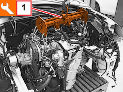
- Fit a suitable bracket for power unit lifting on the exhaust manifold side. |
  |
1. Support the power unit using a hydraulic hoist and the tool connected to the mounting brackets.
|
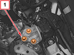  |
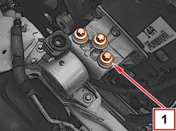
1. Undo the screws fixing the flexible mounting to the gearbox side rigid power unit support. |
  |
1. Undo the screws fixing the flexible mounting to the timing side rigid power unit support. |
|
|
- Remove the power unit from the engine compartment and position it to a platform. - Release the power unit from the support tools. |
|
|
Refitting
(
Removing
)
PARTICOLARI DA SOSTITUIRE SISTEMATICAMENTE
|
|
|
- Fit the support tools to the power unit. - Place the power unit in its housing using a suitable hydraulic hoist. |
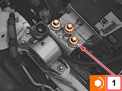  |
1. Tighten the screws fixing the flexible mounting to the timing side rigid power unit support to the prescribed torque.
|
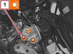  |
1. Tighten the screws fixing the flexible mounting to the gearbox side rigid power unit support to the prescribed torque.
|
|
|
- Remove the hydraulic hoist and tool used for supporting the power unit. - Refit the three-way connector in its seat and secure with the retaining clip. - Place the vibration damper complete with hose back in its housing and attach the retaining clip. - Connect the delivery hose to the three-way connector and attach the retaining clip. - Connect the starter supply lead and tighten the nut. - Connect the gear selector and engagement cables to the reaction bracket attaching the retaining clips. - Connect the gear selector and engagement cables to the gearbox levers. - Connect the battery earth lead and tighten the relevant screw. - Connect the electrical connector for the reverse light switch. - Connect the electrical connection for the engine management control unit. - Connect the engine intermediate coupling. - Connect the quick connectors for the coolant supply and return pipes, heater side. - Engage the coolant fluid pipe retaining clip on the right side panel. - Connect the intermediate quick connector of the coolant fluid pipe and engage the relevant retaining clip. - Connect the coolant pipe quick connector. - Connect the fuel vapour pipe quick connector, intake chamber side. - Connect the quick connector for the fuel delivery pipe, fuel distribution manifold side and engage the relevant retaining clip. - Connect the quick connector for the fuel return pipe to the reservoir, pressure regulator side and engage the relevant retaining clip. - Connect the vacuum pump pipe for the brake servo to the intake chamber side and tighten the band. - Place the left driveshaft back in its housing and connect it to the differential. |
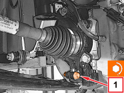  |
1. Tighten the screw securing the front suspension wishbone to the wheel strut to the prescribed torque.
|
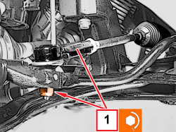  |
1. Connect the steering link to the steering knuckle and tighten the new nut to the specified torque.
|
|
|
Op. 2710A14 RIGHT DRIVESHAFT WITH JOINTS AND INTERMEDIATE DRIVESHAFT - R+R |
|
Op. 1008C34 BRACKET ON GEARBOX FOR LOWER REACTION ROD - R.R. |
|
|
Op. 1076B72 INTERMEDIATE EXHAUST PIPE WITH HOSE SECTION - R+R |
|
Op. 4410D17 REINFORCEMENT FOR FRONT SUSPENSION CROSSMEMBER - R.R. |
|
Op. 1048A50 LOWER ENGINE BLOCK - R.R. CLEAN SEALING SURFACES AND APPLY SEALANT |
|
|
|
|
|
Op. 1048B30 AIR SUPPLY HOSE FROM RIGID PIPE TO THROTTLE BODY - REPLACE |
|
Op. 1048B25 INTERMEDIATE RIGID PIPE BETWEEN HEAT EXCHANGER AND THROTTLE BODY - R R |
|
|
Op. 5050A12 WINDSCREEN WASHER FLUID RESERVOIR FILLER PIPE (IN ENGINE COMPARTMENT) - R.R. |
|
|
|
|
|
|
|
Op. 0010T84 AIR CONDITIONING SYSTEM REFRIGERANT - DEHYDRATING AND REPRESSURIZING |
|
|
|
Op. 0010T64 BRAKE AND/OR CLUTCH FLUID CHECK LEVEL AND TOP UP AS NECESSARY |
|
|
|
Op. 7055B65 ENGINE COMPARTMENT DUST COVER IN LEFT FRONT WHEEL ARCH - R.R. |
|
|
|
|
|
- Remove the vehicle from the lift. |
|
|
1. Using the tool (1a), disconnect the steering rod (1b) from the wheel strut.
|
|
|
1. With a suitable tool, remove the left driveshaft from the differential and secure it to the side. |
|
|
1. Unscrew the brake-clutch fluid reservoir plug and fit the tool.
|
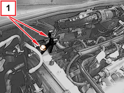  |
1. Undo the screw and remove the fuel pipe retaining bracket. |
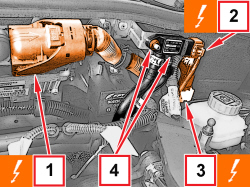  |
1. Disconnect the electrical connection for the engine management control unit.
2. Disconnect the electrical connection from the DPF differential pressure sensor.
3. Disconnect the engine front coupling.
4. Undo the nut and remove the DPF differential pressure sensor from the bracket. |
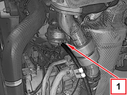  |
1. Disconnect the vacuum pipe from the turbocharger vane control actuator. |
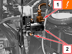  |
1. Disconnect the electrical connection from the turbocharger vane position actuator solenoid valve.
2. Undo the nuts and remove the turbocharger vane position actuator control solenoid valve. |
|
|
1. Retract the clip and remove the additional vibration damper with relevant hose. |
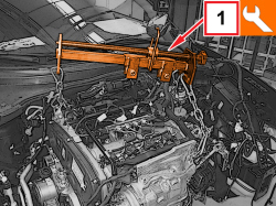  |
1. Support the power unit using a hydraulic hoist and the tool, connected to the mounting brackets.
|