145 - MiTo   1.4 16v TJet   TYRE INFLATION PRESSURE SENSOR (ONE)   4450B90   

Detail     Detail

Removing ( Refitting )

La vettura può essere dotata di sigillante liquido per pneumatici (bomboletta riparagomme), ruotino di scorta o ruota di scorta standard (con o senza il sensore TPMS originale per misurare la pressione dei pneumatici):

- Dispositivo riparagomme (sigillante originale per pneumatici, se presente): dopo aver riparato il pneumatico forato con il sigillante originale per pneumatici, è necessario ripristinare la situazione precedente, in modo che l’impianto spenga la spia indicatrice durante la marcia normale.

- Ruotino di scorta (se presente): il ruotino di scorta non è dotato di un sensore TPMS. Quindi, una volta montato, durante la marcia normale l’impianto accende la spia (lampeggiante per circa 75 secondi, quindi la spia rimane accesa). Questa condizione continua fino a quando non viene montata sulla vettura una ruota dotata di sensore TPMS originale.

- Ruota di ricambio normale senza sensore TPMS: una volta montata, durante la marcia normale l’impianto accende la spia (lampeggiante per circa 75 secondi, quindi la spia rimane sempre accesa). Questa condizione continua fino a quando non viene montata sulla vettura una ruota dotata di sensore TPMS originale. L’impianto viene quindi ripristinato e la spia luminosa si spegne durante la marcia normale.

- Ruota di ricambio normale con sensore TPMS: una volta montata, durante la marcia normale la spia si spegne.

- In tutti i casi sopraindicati, è consigliabile controllare la pressione di gonfiaggio del pneumatico di scorta prima di mettersi alla guida della vettura.

- In caso di sostituzione dei pneumatici, guidando la vettura per brevi periodi, potrebbe essere necessario un pò di tempo prima che l’impianto si ripristini.


- Remove the relevant wheel.

- Remove the valve plug and deflate the tyre.

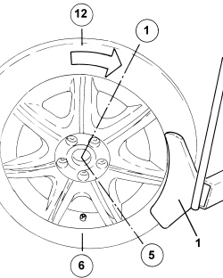
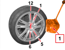
1. Remove the tyre bead with the valve pointing to 6 o'clock and work from 1 o'clock to 5 o'clock.


- Continue to remove the tyre bead working clockwise around the wheel so that the sensor never enters the tool operating area.

- Repeat the above on the inner side of the wheel.

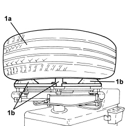
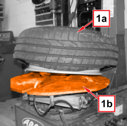
1. Fit the wheel (1a) on the tool chuck (1b), taking care not to attach the rim in the sector where the sensor is located.


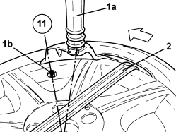
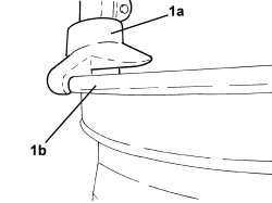
1. Lower the hydraulic arm (1a) to the edge of the rim with the sensor (1b) at 11 o'clock in relation to the hydraulic arm

2. Prise the tyre out of the rim with an appropriate lever.

- Turn the wheel anti-clockwise to prise the tyre bead out of the rim.


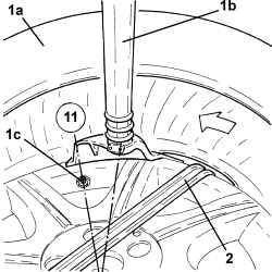
1. Lift the tyre (1a) from the rim, lower the hydraulic arm (1b) on the inner edge with the sensor (1c) at 11 o'clock in relation to the hydraulic arm.

2. Prise the tyre out of the rim with an appropriate lever, turning the wheel anti-clockwise.


- Remove the tyre from the rim.

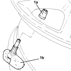
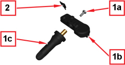
1. Unscrew the nut (1a) securing the sensor (1b) to the rim and remove it.

Always replace the nut every time it is refitted.

When the valve is removed from the rim, it is advisable to replace it because the rubber seal may not fit perfectly in the valve opening later on.


Refitting ( Removing )

- Fit the sensor in its seat, checking that the side pins rest on the rim.

A situation in which only one foot is resting on the rim and the lower part of the sensor is in contact with the rim is acceptable.

Tighten the nut to a torque of 0.34 - 0.46 daNm using an 11 mm hexagonal spanner.

Whilst fitting, make sure that the rubber seal is resting properly on the valve opening and that the valve is correctly aligned with the actual opening, adjusting the angle of the valve in relation to the sensor.

Check that the bolt behind the valve is properly inserted in its housing (the square section of the bolt should be inserted in the housing in the sensor).

During the first stage the fixing bolt behind the valve should be tightened.

Use a manual torque wrench fitted with a special torque setting device. Do not use electric or power screwers.

Tighten until a crack is heard, then continue to tighten until the torque of 0.34 - 0.46 daNm is reached.

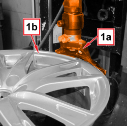
1. Fit the rim on the tool chuck and ensure the hydraulic arm (1a) is in contact with the edge of rim (1b) as shown in the figure.

- Lubricate the entire rim surface and the inner and outer tyre bead area.

- Fit the inner edge of the tyre on the rim using the hydraulic arm.

The initial sensor position must be at 5 o'clock in relation to the hydraulic arm.

- Turn the chuck clockwise and press on the tyre by hand until it is fully fitted.

- During tyre installation, the sensor must stay in the area from 5 o'clock to 7 o'clock.

- Do the same to fit the outer edge.

- Inflate the tyre to the recommended pressure.

- Tighten the plug on the valve and remove the wheel from the tool.

APPLIES TO VERSIONS WITH: M.Y. 2013

Removing ( Refitting )

If the tyre pressure sensor is replaced, the following procedures must be carried out in sequence using the diagnosis equipment:

- Programme ID of tyre sensor concerned

- Carry out the "TPMS sensor roller bench test" procedure.

APPLIES TO VERSIONS WITH: M.Y. 2013

- Remove the relevant wheel.

- Remove the valve plug and deflate the tyre.

APPLIES TO VERSIONS WITH: M.Y. 2013


Enlarge the image


1. Remove the tyre bead with the valve pointing to 6 o'clock and work from 1 o'clock to 5 o'clock.

The distance between the blade of the hydraulic arm and the sensor must always be greater than 80 mm.

APPLIES TO VERSIONS WITH: M.Y. 2013

- Continue to remove the tyre bead working clockwise around the wheel so that the sensor never enters the tool operating area.

- Repeat the above on the inner side of the wheel.

APPLIES TO VERSIONS WITH: M.Y. 2013


Enlarge the image


1. Fit the wheel (1a) on the tool chuck (1b), taking care not to attach the rim in the sector where the sensor is located.

APPLIES TO VERSIONS WITH: M.Y. 2013


Enlarge the image


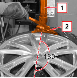
1. Lower the hydraulic arm to the edge of the rim, ensuring that the sensor is at 180° (6 o'clock) in relation to the hydraulic arm.

The distance between the blade of the hydraulic arm and the sensor must always be greater than 80 mm.

2. Prise the tyre out of the rim with an appropriate lever.

- Turn the wheel to prise the tyre bead out of the rim.

APPLIES TO VERSIONS WITH: M.Y. 2013


Enlarge the image


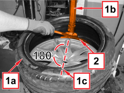
1. Lift the tyre (1a) from the rim, lower the hydraulic arm (1b) on the inner edge with the sensor (1c) at 180° (6 o'clock) in relation to the hydraulic arm.

The distance between the blade of the hydraulic arm and the sensor must always be greater than 80 mm.

2. Prise the tyre out of the rim with an appropriate lever, turning the wheel.

APPLIES TO VERSIONS WITH: M.Y. 2013

- Remove the tyre from the rim.

APPLIES TO VERSIONS WITH: M.Y. 2013


Enlarge the image


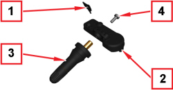
1. Unscrew the nut (1a) securing the sensor (1b) to the rim and remove it.

2. Rimuovere la guarnizione.

When refitting, always replace the fixing nut with a new one in good condition.

APPLIES TO VERSIONS WITH: M.Y. 2013

When the valve is removed from the rim, it is necessary to replace it with a new one in good condition because the rubber seal may not fit perfectly in the valve opening later on.

APPLIES TO VERSIONS WITH: M.Y. 2013


Enlarge the image


Refitting ( Removing )

1. Riporre nella sua sede la guarnizione.

2. Posizionare il sensore, sul lato interno del cerchio, in corrispondenza dell’apposito foro.

3. Inserire la valvola di gonfiaggio sul lato esterno del cerchio.

4. Serrare la vite di fissaggio sensore alla valvola di gonfiaggio.

Prima del serraggio della vite, verificare che ci sia un completo contatto tra la parte anteriore del sensore e la superficie del cerchio attorno al foro valvola.

APPLIES TO VERSIONS WITH: M.Y. 2013


Enlarge the image


1. Fit the rim on the tool chuck and ensure the hydraulic arm (1a) is in contact with the edge of rim (1b) as shown in the figure.

APPLIES TO VERSIONS WITH: M.Y. 2013

- Lubricate the entire rim surface and the inner and outer tyre bead area.

- Fit the inner edge of the tyre on the rim using the hydraulic arm.

The initial sensor position must be at 6 o'clock in relation to the hydraulic arm.

The distance between the blade of the hydraulic arm and the sensor must always be greater than 80 mm.

- Turn the chuck and press on the tyre by hand until it is fully fitted.

- Do the same to fit the outer edge.

- Inflate the tyre to the recommended pressure.

- Tighten the plug on the valve and remove the wheel from the tool.