|
STEP |
CHECK TO BE PERFORMED |
REMEDIAL ACTION IF THE CHECK IS NOT OK |
|
1 |
Aerial power supply signal check Prepare the diagnostic equipment to download a voltage graph. Select the VOLTMETER function from the INSTRUMENT menu with the time set at 1 minute Connect pin 3 (positive) to pin 1 (earth) of the transmitter aerial Press the START button on the diagnostic equipment to begin downloading a graph. Check that the signal pattern corresponds to the attached graph. See E7060 TYRE INFLATION PRESSURE CONTROL SYSTEM Move on to Step 2 |
Restore the continuity of the wiring between the TPMS control unit and the aerial Restore the insulation of the wiring between the TPMS control unit and the aerial Replace the aerial Replace the TPMS Control Unit |
|
2 |
Aerial signal check Prepare the diagnostic equipment to download a voltage graph. Select the VOLTMETER mode from the INSTRUMENT menu with the time set at 3 Connect pin 2 to pin 1 (earth) of the transmitter aerial Press the START button on the diagnostic equipment to begin downloading a graph. Check that the signal pattern corresponds to the attached graph. |
Restore the continuity of the wiring between the TPMS control unit and the aerial Restore the insulation of the wiring between the TPMS control unit and the aerial Replace the aerial Replace the TPMS Control Unit |
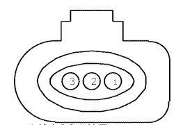
Aerial connector
|
Pin |
Function |
|
1 |
Earth |
|
2 |
Signal |
|
3 |
Fuel system |
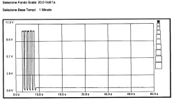
Transmitter aerial power supply signal
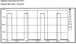
Aerial output signal