145 - MiTo   1.4 16v TJet   MAIN BODY COMPUTER/JUNCTION UNIT - R.R.   5505A35   

Detail     Detail

Removing ( Refitting )

   Op. 7040A37 FUSE BOX COVER IN INSTRUMENT PANEL - R.R


Enlarge the image


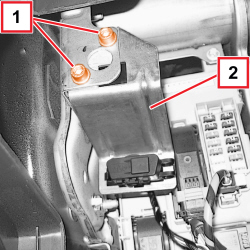
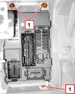
1. Unscrew the bolts.

2. Move the diagnostic socket mount.


Enlarge the image


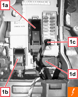
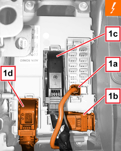
1. Disconnect the frontal electrical connections (1a, 1b, 1c, 1d).


Description


Connector


1


BODY COMPUTER


   See M001 BODY COMPUTER


Enlarge the image


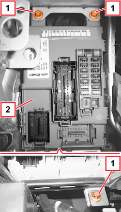
1. Unscrew the bolts.

2. Move the body computer/fusebox.


Enlarge the image


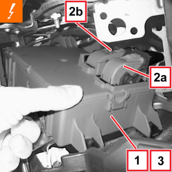
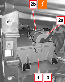
1. Move the body computer/main junction unit slightly.

2. Disconnect the electrical connections (2a, 2b).


Description


Connector


2


BODY COMPUTER


   See M001 BODY COMPUTER

3. Recover the body computer/main junction unit.

Refitting ( Removing )

- Check that the body computer/main junction unit assembly is not damaged.

- Connect the rear electrical connections.

- Position the body computer/main junction unit assembly and tighten the bolts.

- Connect the front electrical connections.

- Position the diagnostic socket support.

- Screw in the bolts.

- If the body computer is being replaced, proceed as follows.

If the Body Computer is being replaced, an identical copy of the Body Computer must be obtained from the Parts Dept. as a V.O.R. order, quoting the vehicle chassis number: this copy will contain all the default settings entered when the vehicle was new which are stored in the Parts Dept. database for the vehicle chassis number.

- If the same body computer that was removed is being refitted on the vehicle, use the Examiner to check that the system has not picked up errors during the operation.

- Check that the electrical system is working.

   Op. 7040A37 FUSE BOX COVER IN INSTRUMENT PANEL - R.R

APPLIES TO VERSIONS WITH: Right-hand drive

Removing ( Refitting )

   Op. 7040A43 HARNESS COVER (ONE – ANY) UNDER DASHBOARD - R.R.

   Op. 7040A31 DASHBOARD COMPARTMENT ASSEMBLY - R.R.

APPLIES TO VERSIONS WITH: Right-hand drive


Enlarge the image


1. Detach the front electrical connections (1a, 1b, 1c, 1d) from the body computer/control unit assembly.


Description


Connector


1


BODY COMPUTER


   See M001 BODY COMPUTER

APPLIES TO VERSIONS WITH: Right-hand drive


Enlarge the image


1. Undo the screws fixing the the body computer/control unit assembly.

APPLIES TO VERSIONS WITH: Right-hand drive


Enlarge the image


1. Move the body computer/control unit assembly slightly.

2. Disconnect the rear electrical connections (2a, 2b).


Description


Connector


2


BODY COMPUTER


   See M001 BODY COMPUTER

3. Recover the body computer/control unit assembly.

APPLIES TO VERSIONS WITH: Right-hand drive

Refitting ( Removing )

- Check that the body computer/control unit assembly is not damaged.

- Connect the rear electrical connections.

- Position the body computer/control unit assembly.

- Screw in the bolts.

- Connect the front electrical connections.

   Op. 7040A31 DASHBOARD COMPARTMENT ASSEMBLY - R.R.

   Op. 7040A43 HARNESS COVER (ONE – ANY) UNDER DASHBOARD - R.R.

- If the body computer is being replaced, proceed as follows.

If the Body Computer is being replaced, an identical copy of the Body Computer must be obtained from the Parts Dept. as a V.O.R. order, quoting the vehicle chassis number: this copy will contain all the default settings entered when the vehicle was new which are stored in the Parts Dept. database for the vehicle chassis number.

- If the same body computer that was removed is being refitted on the vehicle, use the Examiner to check that the system has not picked up errors during the operation.

- Check that the electrical system is working.