
 Removing
(
Refitting
Removing
(
Refitting )
)
 | This procedure is valid only for the 120 HP version. |
|
|
Removing
(
Refitting
)
|
|
|
- Position the left driveshaft in a vice fitted with protective jaws. |
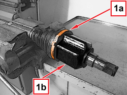  |
1. Loosen the band (1a) and disconnect the differential left inner driveshaft (1b). |
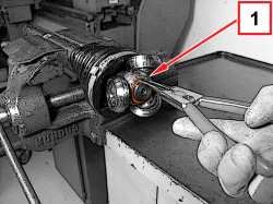  |
1. Remove the retaining ring. |
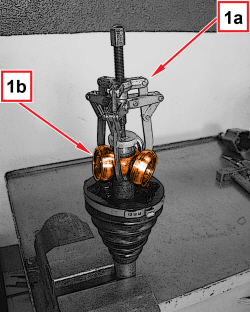  |
1. With an extractor (1a), remove the tripod sliding joint (1b) from the driveshaft. |
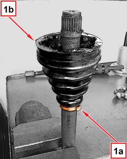  |
1. Loosen the band (1a) and remove the protective boot (1b). |
|
|
Refitting
(
Removing
)
- Position the left driveshaft in a vice fitted with protective jaws. - Place a new protective boot in its housing and fasten it using the band. |
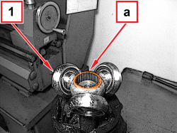  |
1. Place the tripod sliding joint in its housing, making sure the surface (a) is in the position shown in the figure. |
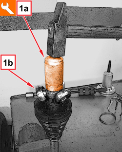  |
1. With the tool (1a), install the tripod sliding joint (1b).
|
|
|
- Install the retaining ring for the tripod sliding joint. |
|
|
- Fill the protective boot with the prescribed grease.
|
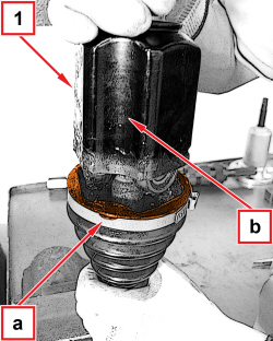  |
1. Place the differential inner driveshaft in its housing and make sure the edges (a) of the boot correspond to the notches (b). |
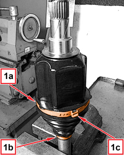  |
1. Tighten the clamps (1a) and (1b).
|
|
|
- Remove the left driveshaft from the vice. |
|
|
Removing
(
Refitting
)
|
|
|
- Position the left driveshaft in a vice fitted with protective jaws. |
|
|
1. Loosen the band (1a) and disconnect the differential left inner driveshaft (1b). |
|
|
1. Remove the retaining ring. |
|
|
1. With an extractor (1a), remove the tripod sliding joint (1b) from the driveshaft. |
|
|
1. Loosen the band (1a) and remove the protective boot (1b). |
|
|
Refitting
(
Removing
)
- Position the left driveshaft in a vice fitted with protective jaws. - Place a new protective boot in its housing and fasten it using the band. |
|
|
1. Place the tripod sliding joint in its housing, making sure the surface (a) is in the position shown in the figure. |
|
|
1. With the tool (1a), install the tripod sliding joint (1b).
|
|
|
- Install the retaining ring for the tripod sliding joint. |
|
|
- Fill the protective boot with the prescribed grease.
|
|
|
1. Place the differential inner driveshaft in its housing and make sure the edges (a) of the boot correspond to the notches (b). |
|
|
1. Tighten the clamps (1a) and (1b).
|
|
|
- Remove the left driveshaft from the vice. |