145 - MiTo   1.4 16v TJet   SYSTEM CABLE LOOM - R.R.   1056B90   

Detail     Detail

Removing ( Refitting )

- Position the vehicle on a lift.

    Op. 1016A10 SOUND-PROOFING COVER - R.R

    Op. 5530B10 BATTERY - R+R

    Op. 5530B52 BATTERY SUPPORT/DRIP TRAY - R.R

    Op. 1032D26 FRONT TIMING PROTECTIVE COVER (UPPER PART) - R.R.

    Op. 1048B30 AIR SUPPLY HOSE FROM RIGID PIPE TO THROTTLE BODY - REPLACE


Enlarge the image


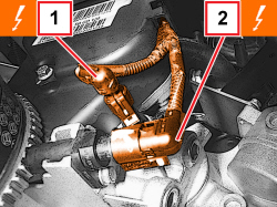
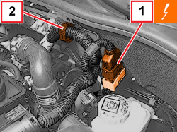
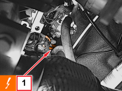
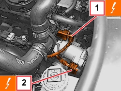
1. Disconnect the electrical connection for the engine oil pressure switch.


Description


Connector


1


Engine oil pressure sensor (switch)


   See K030 ENGINE OIL PRESSURE SENSOR (SWITCH)

2. Detach the rpm sensor electrical connection.


Description


Connector


2


Rpm sensor


   See K046 RPM SENSOR


Enlarge the image


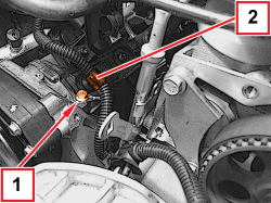
1. Undo the bolt and disconnect the earth lead.

2. Release the wiring retaining clip from the intake chamber.


Enlarge the image


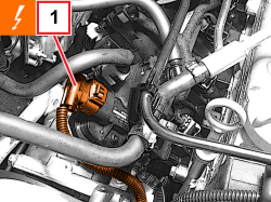
1. Disconnect the electrical connection for the air temperature/pressure sensor.


Description


Connector


1


Integrated air temperature sensor


   See K043 INTEGRATED AIR TEMPERATURE SENSOR


Enlarge the image


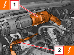
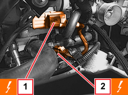
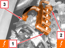
1. Disconnect the electrical connection for the injection/ignition control unit.


Description


Connector


1


Engine management control unit


   See M010 ENGINE MANAGEMENT CONTROL UNIT

2. Disconnect the injector wiring coupling.


Description


Connector


2


Injector coupling


   See D081 INJECTOR JUNCTION


Enlarge the image


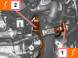
1. Disconnect the intermediate engine wiring coupling.


Description


Connector


1


Front/engine coupling


   See D004 FRONT/ENGINE COUPLING

2. Release the wiring from the retaining clip.

    Op. 7055B54 PROTECTION/GUARD UNDER ENGINE -R.R.


Enlarge the image


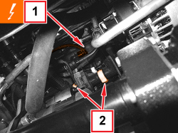
1. Disconnect the electrical connection for the fuel vapour solenoid valve.


Description


Connector


1


Fuel vapour recovery solenoid valve


   See L010 FUEL VAPOUR RECOVERY SOLENOID VALVE

2. Open the wiring retaining clips on the intake chamber.


Enlarge the image


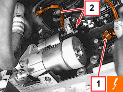
1. Disconnect the electrical connection for the detonation sensor.


Description


Connector


1


Detonation sensor


   See K050 DETONATION SENSOR

2. Lift up the protection, undo the nut and remove the starter motor earth and supply lead.


Enlarge the image


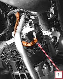
1. Undo the nut and disconnect the alternator earth lead.


Enlarge the image


1. Disconnect the electrical connection for the air conditioning compressor engagement solenoid valve.


Description


Connector


1


Air conditioning compressor engagement electro-magnet


   See L020 AIR CONDITIONING COMPRESSOR ENGAGEMENT SOLENOID


Enlarge the image


1. Disconnect the turbocharging air by-pass valve electrical connection.


Description


Connector


1


Turbocharger by-pass solenoid


   See L102 TURBOCHARGER BY-PASS SOLENOID VALVE

2. Detach the electrical connection for the throttle body.


Description


Connector


2


Integrated throttle body actuator


   See N075 INTEGRATED THROTTLE BODY ACTUATOR


Enlarge the image


1. Disconnect the electrical connection for the rear Lambda sensor to the catalytic converter.


Description


Connector


1


Lambda sensor on catalytic converter


   See K017 LAMBDA SENSOR ON CATALYZER

2. Detach the electrical connection for the engine coolant temperature sensor.


Description


Connector


2


Engine coolant temperature sensor/sender unit


   See K036 ENGINE COOLANT TEMPERATURE SENSOR/SENDER UNIT


Enlarge the image


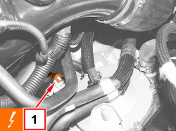
1. Disconnect the electrical connection for the air pressure sensor.


Description


Connector


1


Turbocharging sensor


   See K082 SUPERCHARGING SENSOR

2. Disconnect the electrical connection for the front Lambda sensor to the catalytic converter.


Description


Connector


2


Lambda sensor on preconverter


   See K015 LAMBDA SENSOR ON PRE-CATALYZER


Enlarge the image


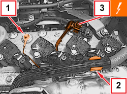
1. Undo the bolt and remove the earth lead from the camshaft housing.

2. Release the oil vapour pipe from the retaining clip.

3. Detach the timing sensor electrical connection.


Description


Connector


3


Timing sensor


   See K047 TIMING SENSOR


Enlarge the image


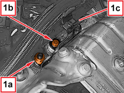
1. Undo the nut (1a) and the bolt (1b) and remove the oil vapour pipe mounting bracket (1c).


Enlarge the image


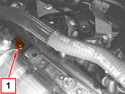
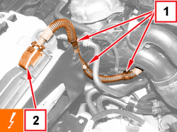
1. Undo the bolt securing the wiring duct to the camshaft housing.


Enlarge the image


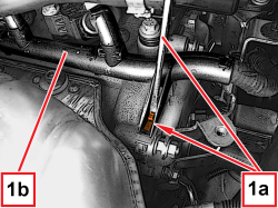
1. Adjust the clip (1a) and release the wiring duct (1b).


Enlarge the image


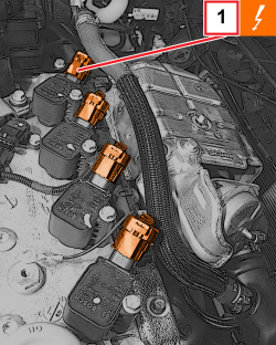
1. Disconnect the electrical connections for the ignition coils.


Description


Connector


1


Ignition coil


   See A030 IGNITION COIL

- Remove the engine wiring.

Refitting ( Removing )

- Refit the engine wiring.

- Connect the electrical connections for the ignition coils, attach the retaining clip and tighten the bolt securing the wiring duct to the camshaft housing.

- Place the oil vapour pipe mounting bracket in its housing and tighten the fastenings.

- Attach the oil vapour pipe to the retaining clip.

- Secure the electrical connection for the timing sensor.

- Place the earth lead in position on the camshaft housing and tighten the bolt.

- Connect the electrical connection for the front Lambda sensor to the catalytic converter.

- Connect the electrical connection for the air pressure sensor.

- Connect the electrical connection for the engine coolant temperature sensor.

- Connect the electrical connection for the rear Lambda sensor to the catalytic converter.

- Connect the electrical connection for the throttle body.

- Connect the turbocharging air by-pass valve electrical connection.

- Connect the electrical connection for the air conditioning compressor engagement solenoid valve.

- Connect the alternator earth lead and tighten the nut.

- Place the starter motor earth and supply lead in position and tighten the nut.

- Close the starter motor wiring protection.

- Connect the electrical connection for the detonation sensor.

- Close the wiring retaining clips on the intake chamber.

- Connect the electrical connection for the fuel vapour solenoid valve.

   Op. 7055B54 PROTECTION/GUARD UNDER ENGINE -R.R.

- Attach the wiring to the retaining clip.

- Connect the intermediate engine wiring coupling.

- Connect the injector wiring coupling.

- Connect the electrical connection for the injection/ignition control unit.

- Connect the electrical connection for the air pressure/temperature sensor.

- Attach the wiring retaining clip to the intake chamber.

- Connect the earth lead and tighten the bolt.

- Secure the electrical connection for the rpm sensor.

- Connect the electrical connection for the engine oil pressure switch.

    Op. 1048B30 AIR SUPPLY HOSE FROM RIGID PIPE TO THROTTLE BODY - REPLACE

    Op. 1032D26 FRONT TIMING PROTECTIVE COVER (UPPER PART) - R.R.

    Op. 5530B52 BATTERY SUPPORT/DRIP TRAY - R.R

    Op. 5530B10 BATTERY - R+R

    Op. 1016A10 SOUND-PROOFING COVER - R.R

- Remove the vehicle from the lift.

APPLIES TO VERSIONS WITH: GPL, Euro 5

Removing ( Refitting )

- Place the car on a lift.

APPLIES TO VERSIONS WITH: GPL, Euro 5

    Op. 1016A10 SOUND-PROOFING COVER - R.R

    Op. 5530B10 BATTERY - R+R

    Op. 5530B52 BATTERY SUPPORT/DRIP TRAY - R.R

    Op. 1032D26 FRONT TIMING PROTECTIVE COVER (UPPER PART) - R.R.

    Op. 1048B30 AIR SUPPLY HOSE FROM RIGID PIPE TO THROTTLE BODY - REPLACE

APPLIES TO VERSIONS WITH: GPL, Euro 5


Enlarge the image


1. Disconnect the electrical connection for the engine oil pressure switch.


Denomination


Connector


1


Engine oil pressure sensor (switch)


   See K030 ENGINE OIL PRESSURE SENSOR (SWITCH)

2. Detach the rpm sensor electrical connection.


Denomination


Connector


2


Rpm sensor


   See K046 RPM SENSOR

APPLIES TO VERSIONS WITH: GPL, Euro 5


Enlarge the image


1. Undo the bolt and disconnect the earth lead.

2. Release the wiring retaining clip from the intake chamber.

APPLIES TO VERSIONS WITH: GPL, Euro 5


Enlarge the image


1. Disconnect the electrical connection for the air temperature/pressure sensor.


Denomination


Connector


1


Integrated air temperature sensor


   See K043 INTEGRATED AIR TEMPERATURE SENSOR

APPLIES TO VERSIONS WITH: GPL, Euro 5


Enlarge the image


1. Disconnect the electrical connections for the LPG injectors.


Denomination


Connector


1


LPG injector


   See N073 LGP ELECTRIC INJECTOR

2. Disconnect the electrical connection for the LPG temperature and pressure sensor.


Denomination


Connector


2


LPG pressure and temperature sensor


   See K215 LPG PRESSURE AND TEMPERATURE SENSOR

3. Open the LPG injector wiring retaining clip.

APPLIES TO VERSIONS WITH: GPL, Euro 5


Enlarge the image


1. Disconnect the electrical connection for the injection/ignition control unit.


Denomination


Connector


1


Engine management control unit


   See M010 ENGINE MANAGEMENT CONTROL UNIT

2. Disconnect the injector wiring coupling.


Denomination


Connector


2


Injector coupling


   See D081 INJECTOR JUNCTION

APPLIES TO VERSIONS WITH: GPL, Euro 5


Enlarge the image


1. Disconnect the intermediate engine wiring coupling.


Denomination


Connector


1


Front/engine coupling


   See D004 FRONT/ENGINE COUPLING

2. Release the wiring from the retaining clip.

APPLIES TO VERSIONS WITH: GPL, Euro 5

    Op. 7055B54 PROTECTION/GUARD UNDER ENGINE -R.R.

APPLIES TO VERSIONS WITH: GPL, Euro 5


Enlarge the image


1. Disconnect the electrical connector for the fuel vapour solenoid valve.


Denomination


Connector


1


Fuel vapour recovery solenoid valve


   See L010 FUEL VAPOUR RECOVERY SOLENOID VALVE

2. Open the wiring retaining clips on the intake chamber.

APPLIES TO VERSIONS WITH: GPL, Euro 5


Enlarge the image


1. Disconnect the electrical connection for the knock sensor.


Denomination


Connector


1


Knock sensor


   See K050 DETONATION SENSOR

2. Lift up the protection, undo the nut and remove the starter motor earth and supply lead.

APPLIES TO VERSIONS WITH: GPL, Euro 5


Enlarge the image


1. Undo the nut and disconnect the alternator earth lead.

APPLIES TO VERSIONS WITH: GPL, Euro 5


Enlarge the image


1. Disconnect the electrical connection for the air conditioning compressor engagement solenoid valve.


Denomination


Connector


1


Air conditioning compressor engagement electro-magnet


   See L020 AIR CONDITIONING COMPRESSOR ENGAGEMENT SOLENOID

APPLIES TO VERSIONS WITH: GPL, Euro 5


Enlarge the image


1. Disconnect the turbocharging air by-pass valve electrical connection.


Denomination


Connector


1


Turbocharger by-pass solenoid


   See L102 TURBOCHARGER BY-PASS SOLENOID VALVE

2. Detach the electrical connection for the throttle body.


Denomination


Connector


2


Integrated throttle body actuator


   See N075 INTEGRATED THROTTLE BODY ACTUATOR

APPLIES TO VERSIONS WITH: GPL, Euro 5


Enlarge the image


1. Disconnect the electrical connection for the rear oxygen sensor to the catalytic converter.


Denomination


Connector


1


Oxygen sensor on catalytic converter


   See K017 LAMBDA SENSOR ON CATALYZER

2. Detach the electrical connection for the engine coolant temperature sensor.


Denomination


Connector


2


Engine coolant temperature sensor/sender unit


   See K036 ENGINE COOLANT TEMPERATURE SENSOR/SENDER UNIT

APPLIES TO VERSIONS WITH: GPL, Euro 5


Enlarge the image


1. Disconnect the electrical connection for the air pressure sensor.


Denomination


Connector


1


Turbocharging sensor


   See K082 SUPERCHARGING SENSOR

2. Disconnect the electrical connection for the front oxygen sensor to the catalytic converter.


Denomination


Connector


2


Oxygen sensor on pre-catalytic converter


   See K015 LAMBDA SENSOR ON PRE-CATALYZER

APPLIES TO VERSIONS WITH: GPL, Euro 5


Enlarge the image


1. Undo the bolt and remove the earth lead from the camshaft housing.

2. Release the oil vapour pipe from the retaining clip.

3. Detach the timing sensor electrical connection.


Denomination


Connector


3


timing sensor


   See K047 TIMING SENSOR

APPLIES TO VERSIONS WITH: GPL, Euro 5


Enlarge the image


1. Undo the nut (1a) and the screw (1b) and remove the oil vapour pipe mounting bracket (1c).

APPLIES TO VERSIONS WITH: GPL, Euro 5


Enlarge the image


1. Undo the bolt securing the wiring duct to the camshaft housing.

APPLIES TO VERSIONS WITH: GPL, Euro 5


Enlarge the image


1. Adjust the clip (1a) and release the wiring duct (1b).

APPLIES TO VERSIONS WITH: GPL, Euro 5


Enlarge the image


1. Disconnect the electrical connections for the ignition coils.


Denomination


Connector


1


Ignition coil


   See A030 IGNITION COIL

APPLIES TO VERSIONS WITH: GPL, Euro 5


Enlarge the image


1. Open the LPG injection system control unit wiring retaining clips.

2. Disconnect the electrical connection from the LPG injection system control unit.


Denomination


Connector


2


LPG ECU


   See M018 LGP UNIT

APPLIES TO VERSIONS WITH: GPL, Euro 5


Enlarge the image


1. Disconnect the electrical connection for the LPG cut out solenoid valve on the pressure regulator.


Denomination


Connector


1


LPG cut out solenoid valve


   See L063 GPL CUT OUT SOLENOID VALVE

APPLIES TO VERSIONS WITH: GPL, Euro 5

- Remove the engine wiring.

APPLIES TO VERSIONS WITH: GPL, Euro 5

Refitting ( Removing )

- Refit the engine wiring.

- Connect the electrical connection for the LPG cut out solenoid valve on the pressure regulator.

- Connect the electrical connection for the LPG injection system control unit.

- Close the LPG injection system control unit wiring retaining clips.

- Connect the electrical connections for the ignition coils, attach the retaining clip and tighten the bolt securing the wiring duct to the camshaft housing.

- Place the oil vapour pipe mounting bracket back in its housing and tighten the fastenings.

- Engage the oil vapour pipe with the retaining clip.

- Connect the electrical connection for the timing sensor.

- Place the earth lead in position on the camshaft housing and tighten the bolt.

- Connect the electrical connection for the front oxygen sensor to the catalytic converter.

- Connect the electrical connection for the air pressure sensor.

- Connect the electrical connection for the engine coolant temperature sensor.

- Connect the electrical connection for the rear oxygen sensor to the catalytic converter.

- Connect the electrical connection for the throttle body.

- Connect the turbocharging air by-pass valve electrical connection.

- Connect the electrical connection for the climate control system compressor engagement solenoid valve.

- Connect the alternator earth lead and tighten the nut.

- Place the starter motor earth and supply lead in position and tighten the nut.

- Close the starter motor wiring protection.

- Connect the electrical connection for the knock sensor.

- Close the wiring retaining clips on the intake chamber.

- Connect the electrical connection for the fuel vapour solenoid valve.

   Op. 7055B54 PROTECTION/GUARD UNDER ENGINE -R.R.

- Attach the wiring to the retaining clip.

- Connect the intermediate engine wiring coupling.

- Connect the injector wiring junction.

- Connect the electrical connection for the injection/ignition control unit.

- Close the LPG injector wiring retaining clip.

- Connect the electrical connection for the LPG temperature and pressure sensor.

- Connect the electrical connections for the LPG injectors.

- Connect the electrical connection for the air pressure/temperature sensor.

- Attach the wiring retaining clip to the intake chamber.

- Connect the earth lead and tighten the screw.

- Connect the electrical connection for the rpm sensor.

- Connect the electrical connection for the engine oil pressure switch.

APPLIES TO VERSIONS WITH: GPL, Euro 5

    Op. 1048B30 AIR SUPPLY HOSE FROM RIGID PIPE TO THROTTLE BODY - REPLACE

    Op. 1032D26 FRONT TIMING PROTECTIVE COVER (UPPER PART) - R.R.

    Op. 5530B52 BATTERY SUPPORT/DRIP TRAY - R.R

    Op. 5530B10 BATTERY - R+R

    Op. 1016A10 SOUND-PROOFING COVER - R.R

APPLIES TO VERSIONS WITH: GPL, Euro 5

- Remove the vehicle from the lift.