


VEHICLE REPAIRS
Vehicle identification data
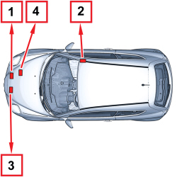
The vehicle is equipped with the following identification plates:
-
1. V.I.N. Plate
-
2. Body marking
-
3. Body paintwork identification plate.
-
4. Engine marking
Vehicle towing points
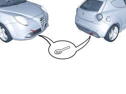
The vehicle is equipped with two threaded seats, one at the front and one at the rear, for the installation of the tow hook present in the housing inside the spare wheel, located in the boot under the carpet.

|
When towing the vehicle, it is compulsory to respect specific highway code regulations relating to the tow hook and procedures for towing on the road. Clean the threaded seat carefully before tightening the hook. Before towing, make sure that the tow hook is fully tightened. Ensure that the electronic key is inserted in the TEG Reader If the key is extracted, the steering lock will come on automatically and it will be impossible to steer the wheels. If the battery has to be disconnected, only carry out the operation with the electronic key inserted in the TEG Reader. This avoids the need to engage the steering lock. With the engine switched off, neither the brake servo nor the power steering are working so greater effort is required on both the brake pedal and the steering wheel. |
Vehicle lifting points
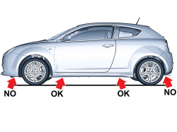
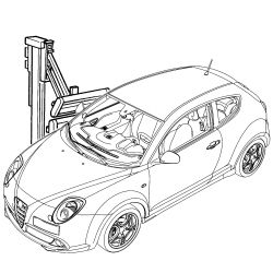
To raise the vehicle using an arm lift or a workshop lift, arrange the ends of the arms or the lift in the areas shown in the diagram only.
|
|
Before raising the vehicle using portable lifts, lock the wheels by placing chocks in front of (behind) the front (rear) wheels. After having raised the vehicle, support it using safety stands. |
General safety instructions
The activities related to the bodywork repair operations involve the use of specialist equipment as well as the handling of chemical products, which must be done in accordance with the supplier's recommendations.
Special attention should therefore be paid to:
-
The correct use of materials, instruments and equipment: before carrying out any operation, read the instruction manuals very carefully and follow the directions and recommended accident prevention regulations scrupulously.
-
Specially designated work areas must be equipped with a ventilation system that meets standards for air exchange, filtration of harmful substances (solvents) and keeping down dust levels.
-
Dangerous substances that have to be used must be handled following the supplier's instructions and recommendations. *-The collection and disposal of waste must be carried out in accordance with current legislation.
Whilst working with and handling dangerous substances, the appropriate accident prevention measures must be taken (wearing protective clothing, masks, gloves, goggles, etc.).
Vehicle repair operating cycles
The vehicle repair operating cycles usually consist of the following stages:
-
checking vehicle measurements;
-
cutting/removing damaged elements and preparing the body for welding;
-
welding replacement parts;
-
preparing for painting;
-
painting;
-
restoring anti corrosion conditions,
-
sound insulation, sealants.
This is the first stage of the repair operation during which the distortion suffered by the body is measured and evaluated and the elements involved are identified.
The first actual repair operation is also carried out during this stage: stretching the body to restore the correct dimensions before cutting and removing the damaged elements.
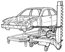
Stretching the bodyStretching the body to restore its dimensions is carried out on the alignment benches, where it is possible to secure the body using vices and mountings to be fitted in accordance with the specific instructions for each vehicle, which come with the bench.
Templates, positioned in the recommended places, are used to check the body measurements either using the measurements given by the manufacturer of the template for each model or, alternatively, those for the vehicle given in the "Description and Operation" section.
Example of a possible alignment bench configuration.
General repair instructions
| The battery leads must be disconnected before carrying out any operation on the vehicle. |
| I morsetti della batteria devono essere scollegati solo con chiave di avviamento su STOP o estratta, mai con chiave su MAR o con motore avviato. Lo stacco dei morsetti deve comunque essere effettuato dopo aver atteso almeno 1 minuto dal posizionamento della chiave su STOP. Per versioni con cambio Robotizzato, prima di scollegare i morsetti, accertarsi che la porta lato guida sia chiusa per evitare che la fase di pressurizzazione impianto idraulico, comandata dall'apertura porta, venga interrotta prima del suo completamento. |
For safety reasons and for a better quality repair, IT IS FORBIDDEN TO:
replace the structural parts of the body without using a repair bench. The use of the bench makes it possible to guarantee the restructuring of the vehicle with the original manufacturing measurements, ensuring the correct positioning of the components that make up the forecarriage and the rear part of the vehicle.
heat the structural parts of the body to straighten them.
cut and weld any bodywork element and reinforcement, edge to edge, on the same line.
Remove the damaged components by cutting them along the joints, following the cutting lines given in the Service Manual. Correctly carried out, this operation involves a gap of several centimetres between the two cutting lines in order to distribute the melt spots created by the welding.
The diagram below illustrates a possible implementation.
| Removing the damaged elements is the repair stage during which the most potentially dangerous equipment is used. Before carrying out any operation, read carefully the instruction manual and the safety instructions and warnings given by the manufacturer together with the equipment, and follow all safety precautions most stringently. |
The use of the following is required for removing damaged panels:
power jig saws;
circular saws;
power chisels (only if necessary);
plasma cutting systems;
electric drills;
milling machines for spot weld removal;
grinders;
hammers and dolly blocks;
disc grinders;
air extractor fans.
This type of saw makes it possible to make fast, precision cuts with the possibility of regulating the speed of the blade so that it can be adapted to suit different situations.
Example of the use of a power jig saw
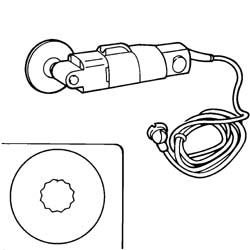
Vibrating circular sawA vibrating saw is used in situations which require high precision cutting; for example, the panel in a box section is to be replaced, overlapping on the panel that should not be damaged. By adjusting the speed and the number of oscillations it is possible to achieve the precision required, according to the usage conditions. The high safety level for this instrument means that it is advisable to use it as an alternative to other types of saws.
Example of a vibrating circular saw
Power chiselPower chisels are used to detach parts of panels and are recommended: *- when it is not possible to use the power saw, chamfering machine or drill, e.g. when another panel lies behind the panel to be cut that must not be damaged. *- when it is possible to separate the welded panel directly by inserting the chisel tip between the two panels along the join, in order not to leave edges to be removed at a later stage.
The different fittings that it comes with increase its versatility.
Example of the use of a power chisel.
Plasma cutting systemThis cutting system, produced through the combined effect of an electrical arc and gas or a gas mixture, is used if very large panels have to be removed. Depending on the thickness of the panel and the depth of the cut, the value of the current and flow of gas can be adjusted in accordance with the instruction manual supplied by the Manufacturer.
| The use of plasma cutting systems requires the use of an extraction system to remove harmful gases and fumes. |
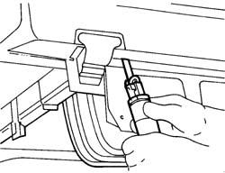
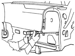
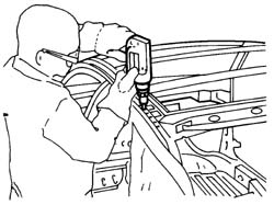
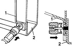
Electric drills are normally used in cases where a milling machine cannot be used; the correct use of the drill for removing weld spots, where panels are overlapping, is illustrated below. The fitting to be used for these operations is identical to the one fitted on the milling machine. The weld spot should be marked using a drift, in order to provide support for the centring point, thereby preventing the cutter from slipping and damaging the surrounding area; the cutter should then be pushed until it reaches slightly deeper than the thickness of the panel to be removed (see diagram below).
Example of the use of an electric drill.
Example of the correct use of a milling machine for spot weld removal.
1 - Panel to be detached.
2 - Box section panel preventing the use of the milling wheel.
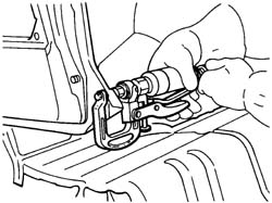
Milling machine for spot weld removalA milling machine for removing spot welds is used after the panel to be replaced has been cut to allow the removal of the metal offcuts remaining on the edges of the body.
The milling machine works on the panel, cutting it as far as the panel underneath and insulating the spot weld.
After removing all the spot welds, the piece cut off can be removed using pliers.
A cutting speed of around 1000 rpm should be used to facilitate the operation.
Adjust the milling depth using the special screw.
Example of the use of a milling machine.
 | Do not drill matching components. If holes have been made accidentally, close them using (MIG) welding. The presence of holes decreases the resistance of the component involved and can also give rise to penetration by water and corrosive agents. |
These instruments are used when panels need to be hammered straight in order to provide a reaction point supporting the panel. The dolly blocks are designed so that they can be adapted to suit the different shapes of the panel and, when the work area permits, they can replace the hammer.
The levers have the same usage instructions as the dolly blocks, however they are designed so that they can be introduced through openings and restricted spaces into areas that are difficult to reach.
Dolly blocks and levers are also used to remove distortions from the edge of panels that are not removed, thereby allowing them to be matched with replaced panels, preventing the structure from being weakened.
Welding replacement parts
.
| If welding or work has to be carried out which could produce flames near the fuel supply system components illustrated in the diagram, or other flammable parts of the vehicle, the parts concerned should be removed from the vehicle and the free connections of the pipes sealed if the connectors are disconnected. Disconnect the electronic control units which could be damaged during the work (i.e., ABS, Air Bag, Air Conditioning, Alarm, etc.). |
Fuel supply system components.
The bodywork components can be welded using different methods:
Spot welding;
Seam welding (MIG);
Brazing.
The following equipment is used for these operations:
welding machines with clamps;
seam welders (MIG);
oxyacetylene torches (brazing).
During spot welding the heat required to melt the metal is provided by the resistance to the flow of current which the metal opposes.
Spot welding is carried out on panels where the join edges are overlapping and takes place through localized fusion of the metal that makes up the panel so no weld metal is required for this type of welding. In areas where three or more panels are overlapping, the spot welding must be repeated a second time.
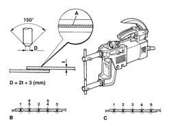
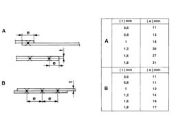
The type of join that is produced is discontinuous; the weld spots must be correctly spaced in order to confer good mechanical resistance, in accordance with the precise instructions (see the tables below).
Spot weldingIn the case of spot welding, check:
that the arms are correctly aligned;
that the diameter of the ends of the electrodes is correct;
the flatness and correct matching of the edges of the weld;
the correct welding sequence.
| Before welding, apply electro-weldable galvanized coating to the edges of the join in order to protect the box sections from corrosion. |
Spot welder, geometric specifications of the electrode depending on the thickness of the panel and the welding sequence.
A - Electro-weldable galvanized coating
B - Correct welding sequence
C- Incorrect welding sequence
D - Size of the electrode
Table of reference values for carrying out spot welding.
A. Table for determining the distance of the spot welds from the edges of the panels according to their thickness.
B. Table of reference values for the correct spacing of spot welds depending on the thickness of the panel.
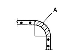
| Do not weld corner shaped surfaces. If welds are made on this type of surface it produces a concentration of tension that causes it to break. |
Example of correct spot welding at corners.
A. Area where welding should not be carried out.
Seam welding (mig)MIG welding should be used for parts where spot welding cannot be used. When seam (MIG) welding, check:
the speed of the wire
the correct execution of the seam welding beads (alternation of welding sections)
In this welding system the electrode (an automatic advance continuous wire) is protected by an atmosphere of inert gases (this is where the initials MIG come from - Metal Inert Gas). - The continuous advance of the wire (which constitutes both the electrode and the weld metal), allows long welds to be made with no interruptions. The flow of inert gases sent to the welding area eliminates the air surrounding the fusion bath, preventing the oxidation of the metal. It also carries out the function of a protective coating for coated electrode welding. For these reasons, MIG welding differs from welding carried out with a coated electrode due to the absence of deposits on the welding seam. Neither is it affected by the porosity that may be seen with normal arc welding.
| The use of MIG welding systems requires use of an extraction system to remove the harmful gases and fumes. |
In order to weld two panels correctly using a MIG welder: sand or dress the panel thoroughly, position the equipment so that whilst carrying out the welding the torch outer casing does not become twisted or folded in such a way that could obstruct the advance of the wire, wear protective clothing and a suitable mask with an anti-glare visor (standard no. 8 glass for currents of 40-60A and no. 9 for currents of 80-200A). Regulate the flow of gas in accordance with the instructions from the equipment's Manufacturer. Make two spot welds at the ends of the join line and one in the middle, then make welds in between the two sections defined in this way. The spot welds should be 25 - 30 mm apart.
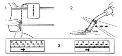
The diagram below shows how to carry out the welding correctly (1).
 | the correct gap is about 1 mm. |
Carrying out welding (2) using an inert gas electrode (MIG) to join adjacent panels.
It is not advisable to seam weld initially because, in addition to being difficult in practical terms, it may cause the panel to become distorted as a result of the build up of heat involved.
The difficulty in carrying out a single seam weld is that the torch must be moved fairly slowly to produce good penetration of the weld but sufficiently quickly so as not to run the risk of "burning" the panel.
Moving the torch too quickly also leads to a poor seal of the weld seam because, after grinding the seam, an insufficient layer of filler material remains to guarantee the resistance of the join.
After initially spot welding the panel, use a rigid disc grinder to grind the weld spots level with the panel.
At this point the alignment of the panels must be checked and, if necessary, corrected using a hammer and steel stake.
Then proceed with filling the gaps between the various spot welds through alternating welding sections, keeping the torch at an angle of about 60' (see previous diagram).
1. Tack welding the join. The tack welds at the back of the panel are illustrated. Grinding the join tack welds.
2. Welding.
3. The illustration shows two alternatives for the correct welding sequence in order to prevent the distortion of the panel.
The advantage of the welding operation is confirmed by the appearance of the rear of the weld seam which should show a series of spherical caps side by side for the entire length of the join.
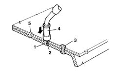
The MIG welder can also be used for joining overlapping panels where only one side is accessible.
To carry out spot welding, the panels must adhere perfectly and the torch must be perpendicular to the surface.
In this way the action of the electrode initially melts the first panel, then the second, where a crater is produced which is filled by the advance of the electrode.
In order to carry out this operation correctly, the welding machine must be regulated to current values that are suitable for the thickness of the panels being worked on with the torch resting on its supports and pressure on the surface to facilitate the panels being brought close together.
If the panels are thicker than 1.5 - 2.5 mm, make an initial 0.6 mm hole at the sites of the spot welds.
Carrying out welding using an inert gas electrode (MIG) to join overlapping panels.
1. Panel join area
2. Electrode
3. Spot weld
4. Torch
5. Hole (only for thick panels)
General rules for visible weldingSome important rules are given below. These should not be underestimated.
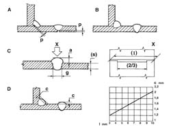
incomplete penetration (p) should be 15-30% of the thickness of the panel (see diagram below - point A incorrect welding, point B correct welding).
the height of the seam (a) should be 60% of the thinnest thickness (s), the clearance (g) between the panels before welding should be 20% of the thinnest thickness for at least two thirds of the length (l) of the seam (see diagram below, point C and detail X). the diagram illustrates the value of the convexity (c) of the seam depending on the length (l) of the weld section.
the convexity (e) of the shape of the weld seam section should depend on the length of the actual seam (see diagram below, point D).
Welding examples.
BrazingBrazing is only used if welded panels have to be replaced and should only be carried out at the points recommended by the Manufacturer.
This type of welding does not guarantee mechanical properties that are comparable with the other systems described previously and should therefore not be used for joining structural elements.
| When using oxyacetylene torches for brazing, observe the following safety rules: the use of this welding system requires an aspiration system for the elimination of harmful fumes and gases to ensure operations are carried out under safe conditions. |
When carrying out work that produces fumes, gas and powder which are dangerous to the mechanic, air filtration and purification systems must be used.
These systems are designed for the various requirements to handle different volumes of air that require purification. The operation of these systems is usually based on the combined action of mechanical and electro-static filtration and purification using activated charcoal. Filtration takes place in two stages: mechanical elimination, using mesh filters, of the largest particles of powder, then ionisation of the air flow, which statically charges the particles of powder. These are then eliminated from the flow through an electrostatic process.
The flow of air is then purified by passing through activated charcoal filters. In these systems, in addition to the specific efficiency, the ease of handling and noise levels have been improved and are never troublesome.
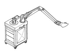
The diagram below illustrates a possible configuration.
Example of mobile air filtration and purification system.
PAINTING
Introduction
Painting the body has two basic objectives: protecting the surfaces of the panels from the elements and an aesthetic function of providing colour and shine.
The large number of chemical products used in painting operations means that special care must be taken over their handling and usage.
These painting operations involve the emission of paint fumes and solvent vapours which, if inhaled by the operator, could constitute a serious danger to health. These operations should therefore only be carried out in spray booths.
The operator should always wear a mask and protective clothing.
For operations that do not take very long, filtration masks should be used; for longer operations, total protection pressurised masks must be used.
EquipmentThe following equipment is used during painting operations:
filtration masks and protective clothing;
masking and taping machines;
spray booths and stoving ovens;
spray guns;
infrared lamps;
polishing machines.
When carrying out painting operations, suitable protective clothing must be worn to protect the operator from contact with harmful substances.
It is also advisable to use a barrier cream on any exposed areas (face, hands, arms), which should be removed at the end of the painting operations.
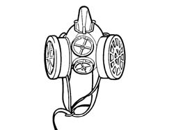
Filtration maskThis type of mask only protects the operator's respiratory system and protective goggles and headgear should also be worn at the same time. Its use is recommended for small retouching operations.
Example of a filtration mask.
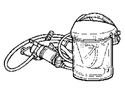
Pressurized maskThis type of mask guarantees protection of the face and hair and is supplied with pure air from the compressed air system used for the spray gun.
The air is purified further with a degree of separation close to 100%, by an activated charcoal filter fitted to the operator's belt.
The slight excess pressure created inside the helmet prevents the penetration of paint vapours.
The use of this mask is advisable for long painting operations. Example of a pressurized mask
Spray boothSpray booths are used for painting operations and for stoving prepared parts. If the extent of the damage repaired is medium or large, it would be helpful to have a special spray booth and a hot air circulation oven for drying the paint.
The area should be equipped with an air conditioning system and filtered by purifiers, mainly comprising activated charcoal filters.
The optimum painting conditions that should be maintained in the booth during the painting stage are as follows:
constant temperature between 22-25 C
consant humidity of 75 - 80%
The area in question could be:
a combined painting and drying booth;
a separate painting booth and drying oven.
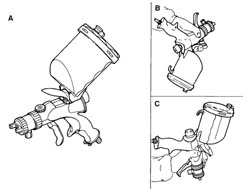
Developments in the study of ergonomics and spray painting techniques have led to a new type of high air volume and low atomisation pressure spray gun that allows a considerable reduction in paint mist. This type of spray gun has been designed to be lighter with a grip that reduces tiredness and eliminates cramp and with controls that require far less effort than conventional spray guns. The handling of the spray gun is also made easier by the even weight distribution and by the improved design that makes it easier to operate. The most interesting aspect of this spray gun is the supply system that allows painting in any direction, even with the cup facing downwards, also improving the cleaning procedures with considerable savings in terms of time and materials. The possibility of painting from the top or the bottom, in addition to preventing the formation of areas that are too wet or too dry, also facilitates access to areas of the bodywork that are difficult to reach. Special care has been taken over the ease of adjustment. This requires minimal, simple movements. This spray gun is extremely efficient, combining a very fine atomization capacity for any product, even water soluble, used by bodyworkers at a pressure of 0.7g (10 PSI) or below. Thanks to these capacities for using paint materials, it has been possible to achieve a considerable economic saving and improved working conditions. The diagram below illustrates some possible uses of the spray gun.
Use of the spray gun.
A - Method of normal usage
B - Use from the bottom to the top
C - Use from the top to the bottom
Portable infrared lampsIf the operation is restricted to small retouches, then the use of an oven is not practical. In these cases the paint can be dried using special infrared lamps fitted on parabolic mirrors. The use of one or more lamps positioned so that the surface that has been retouched is subject to an even temperature allows the paint film to bake and the result is comparable to that achieved in an oven.
This type of lamp greatly reduces drying times, thereby also reducing energy consumption. The lamp should only be used when the paint has already dried to the extent that it is out of the powder stage.
Drying a retouch using a portable infrared lamp.
Polishing machinesThe paint should only be polished after the enamel has been baked and after it has cooled down to ambient temperature.
Polishing is also necessary if there are defects in the paintwork such as dust, paint fumes, drips, orange peel or small scratches.
There are many products that can be applied, either manually or using a polishing machine, to remedy these defects.
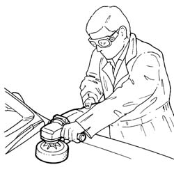
The tool should be parallel to the surface to be polished and should not be at an angle, in order to prevent the paint from overheating and producing circular concentric grooves.
The diagram below illustrates the correct way of holding the polishing machine.
Correct use of the polishing machine.
Painting cycles
It should be pointed out that all painting operations must be carried out using appropriate equipment.
It is advisable to use the specific environmentally-friendly solvents for cleaning the equipment.
There is a silver paintwork identification plate on the vehicle, normally inside the bonnet or the boot lid/tailgate, which contains the original colour identification code for respraying or touching up.
The products used (both those on the plate and recommended by Fiat which may possibly be different) should conform to the laws in force in terms of safety, hygiene and the environment and, failing this, must meet European Community standards. It is the responsibility of the final user to check beforehand that the conditions of usage are compatible with the recommendations in the supplier safety documents.
As far as the practical aspects are concerned, suppliers should certify that the aesthetic/practical features (e.g. mechanical properties, resistance to ageing and protection against corrosion) meet the corporate technical specifications if applied in accordance with the methods indicated in detail in the "product technical chart". Conformity with corporate specifications guarantees that the manufactured article will be in line with the original painting process quality standards.
This certification assumes that the recommendations for the individual products in the Safety Information Chart that the Supplier must give the consumer in accordance with the laws in force in the country (in Italy in line with Legislative Decrees 52/97 and 285/98 and subsequent modifications and additions) are followed to the letter.
Bodywork repairs (panel support)If a body panel is being replaced, check that dimensions, materials and surface treatment (galvanizing, cataphoresis) of the replacement part conform to the Manufacturer's specifications.
| Visually inspect the condition and the suitability of the replacement panel. If there are small negative bubbles, it is permitted, after straightening (as much as possible) using levers, files, etc., to restore the aesthetic appearance through applying putty and levelling out the defect. It can be applied after cleaning the surface (painting through cataphoresis) near the defect; after hardening completely, dry sand with P 180 - P 220 grade abrasive paper. |
Clean the replacement panel with a low volatility organic detergent (VOC) to remove any dust or grease that may be present.
Gently dry sand the entire surface to be painted, using P 320 grade sandpaper and a rotary/orbital power sander equipped with an extractor.
| Take care not to nick/remove the cataphoretic painting. |
Remove any residues of dust using compressed air and clean the entire surface using a low VOC detergent or an anti-static product.
If, during the above operations (point 2), the panel is accidentally exposed by removing the cataphoretic coating or the zinc the anti-corrosion protection must be restored by spraying a high thickness epoxide layer on the areas concerned.
If appropriate, seal the joins by applying (mono or twin component) sealant that hardens at ambient temperature.
Apply a filler, prepared previously following the instructions on the product technical chart, by spraying 2 crossover coats, at intervals of a few minutes, until the thickness recommended on the product technical chart is reached (2 - 4 crossover coats). Wait for 10 to 15 minutes at ambient temperature before starting the drying process.
Dry the base coat in an oven at a temperature of 40° - 60°C for about 30 - 40 minutes.
When it is dry (and the panel is cold), dry sand the surface using P 400 grade sandpaper to remove any defects.
Remove any residues of dust using compressed air and clean the entire surface firstly using a low VOC detergent and then finish off with an anti-static cloth.
Prepare the enamel (single coat or double coat) and/or the transparent resin for spraying following the instructions on the technical chart for the product and use it within the recommended time.
Apply the enamel in 2 crossover coats with a few seconds in between until the desired thickness and colour matching is achieved.
Leave the enamel to dry at ambient temperature, following the instructions on the supplier's technical chart for the time and conditions.
For aesthetic finishes with single coat enamel, dry in the oven at a temperature of 60°C for 40 minutes. Alternatively, dry using an IR ray lamp, following the instructions described by the manufacturer (distance of radiant panel from the surface to be dried; exposure time).
For double layer enamel aesthetic finishes, proceed with the application of the transparent resin (opaque base coat) prepared previously in accordance with the instructions on the technical chart with 2 or 3 crossover coats with intervals of a few seconds in between.
Dry in the oven at a temperature of 60°C for 40 minutes. Alternatively, dry using an IR ray lamp, following the instructions described by the manufacturer (distance of radiant panel from the surface to be dried; exposure time).
Polish the surface at least 24 hours after the last coat has baked (and the panel is cold).
| Before spot welding the panels, apply electro-weldable galvanizing protection to the ground edges of the join area (as described in the Service Manual). |
Clean the replacement panel with a low VOC detergent to remove any dust or grease that may be present.
Secure the replacement panel to the bodywork by welding, protecting the surrounding surfaces/elements by masking and, where possible, removing them.
Wait until the work surfaces have cooled down, then proceed with removing the swarf and oxides that have formed on the surface near the welding seam by brushing and dry sanding with P80 - P120 grade abrasive paper.
If the welding is visible and therefore the aesthetic appearance and the continuity of the profiles needs to be restored, fill the join and when it is completely hard dry sand with P100 - P120 grade sandpaper on a roto-orbital sander.
If, during the above operations the panel is accidentally exposed by removing the cataphoretic coating or the zinc the anti-corrosion protection must be restored by spraying a high thickness epoxide layer on the areas concerned.
Remove any residues of dust using compressed air and clean the entire surface using a low VOC detergent or an anti-static product.
If appropriate, seal the joins by applying (mono or twin component) sealant that hardens at ambient temperature.
Apply a filler, prepared previously following the instructions on the product technical chart, by spraying 2 crossover coats, at intervals of a few minutes, until the thickness recommended on the product technical chart is reached (2 - 4 crossover coats). Wait for 10 to 15 minutes at ambient temperature before starting the drying process.
Dry the base coat in an oven at a temperature of 40° - 60°C for about 30 - 40 minutes.
Inspect the surface as soon as it has been worked on and remove any defects by dry-sanding the surface using P 400 grade sandpaper.
Remove any residues of dust using compressed air and clean the entire surface firstly using a low VOC detergent and then finish off with an anti-static cloth.
Prepare the enamel (single coat or double coat) and/or the transparent resin for spraying following the instructions on the technical chart for the product and use it within the recommended time.
Apply the enamel in 2 crossover coats with a few seconds in between until the desired thickness and colour matching is achieved.
Leave the enamel to dry at ambient temperature, following the instructions on the supplier's technical chart for the time and conditions.
For aesthetic finishes with single coat enamel, dry in the oven at a temperature of 60°C for 40 minutes. Alternatively, dry using an IR ray lamp, following the instructions described by the manufacturer (distance of radiant panel from the surface to be dried; exposure time).
For double layer enamel aesthetic finishes, proceed with the application of the transparent resin prepared previously in accordance with the instructions on the technical chart with 2 or 3 crossover coats with intervals of a few seconds in between.
Dry in the oven at a temperature of 60°C for 40 minutes. Alternatively, dry using an IR ray lamp, following the instructions described by the manufacturer (distance of radiant panel from the surface to be dried; exposure time).
Polish the surface at least 24 hours after the last coat has baked (and the panel is cold).
Protect the areas not involved in the painting operation by masking.
Restore the aesthetic appearance (profile and surface appearance) of the damaged panel. Lastly, level the area worked on using filler which can be applied after cleaning the surface using special detergent if the damage caused has not exposed the panel or, if the panel has been exposed, the corrosion protection should be restored through the local application of the epoxide base coat (see point 6 page 2).
After the filler is completely set, dry sand using P180 - P220 grade sandpaper.
The overhaul the surface to be repainted using P150 or P220 grade sandpaper, extending the perimeter of the area worked on through slight shading outwards taking care to remove any traces of oxidation on the exposed panel.
Remove any residues of dust using compressed air and clean the entire surface using a low VOC detergent or an anti-static product.
If appropriate, seal the joins by applying (mono or twin component) sealant that hardens at ambient temperature.
Apply a filler, prepared previously following the instructions on the product technical chart, by spraying 2 crossover coats, at intervals of a few minutes, until the thickness recommended on the product technical chart is reached (2 - 4 crossover coats). Wait for 10 to 15 minutes at ambient temperature before starting the drying process.
Dry the base coat in an oven at a temperature of 40° - 60°C for about 30 - 40 minutes.
Check the surface as soon as it has been worked on and remove any defects by dry-sanding the surface using P 400 grade sand paper.
Remove any residues of dust using compressed air and clean the entire surface firstly using a low VOC detergent and then finish off with an anti-static cloth.
Prepare the enamel (single coat or double coat) and/or the transparent resin for spraying following the instructions on the technical chart for the product and use it within the recommended time.
Apply the enamel in 2 crossover coats with a few seconds in between until the desired thickness and colour matching is achieved.
Leave the enamel to dry at ambient temperature, following the instructions on the supplier's technical chart for the time and conditions.
For aesthetic finishes with single coat enamel, dry in the oven at a temperature of 60°C for 40 minutes. Alternatively, dry using an IR ray lamp, following the instructions described by the manufacturer (distance of radiant panel from the surface to be dried; exposure time).
For double layer enamel aesthetic finishes, proceed with the application of the transparent resin prepared previously in accordance with the instructions on the technical chart with 2 or 3 crossover coats with intervals of a few seconds in between.
Dry in the oven at a temperature of 60°C for 40 minutes. Alternatively, dry using an IR ray lamp, following the instructions described by the manufacturer (distance of radiant panel from the surface to be dried; exposure time).
Polish the surface at least 24 hours after the last coat has baked (and the panel is cold).
For aesthetic painting with a three coat enamel "nuvola" finish, continue after applying and baking the filler coat. A special (white) covering coat must be applied under the enamel before the nuvola enamel and the clear coat.
Painting operations on plastic elements(Polyolefinic thermoplastic material (PP) e.g. bumper)
Painting a replacement bumper
In the case of replacement, check that the replacement part complies with the corporate technical specifications in terms of dimensions, materials and surface treatment (black base with solvent or water adhesion promoter 3 ± 0.5 gloss with adhesion promoter and aesthetic finish function).
| If there are slight surface defects, the aesthetic appearance can be restored by levelling the defect using filler. This can be applied after cleaning the surface near the defect; after it has hardened completely, dry sand using P 320 - P 400 grade abrasive paper. |
Degrease the bumper as a precaution to remove any dust or grease using detergent (e.g. isopropyl alcohol).
Gently sand the surface using fine grade sandpaper (e.g. P600), taking care not to remove too much of the adhesion promoter film.
| If anti-static liquids are used, first check their compatibility with the black background because some of them may be particularly aggressive and even cause its removal with the result that the aesthetic finish does not adhere. |
Blow through with compressed air (filtered and purified) and clean using anti-static cloths/special detergents.
Mask the areas not being painted in the body tint (e.g. rubbing strips, lower section, etc.).
Prepare the enamel (single coat or double coat) and/or the transparent resin for spraying following the instructions on the technical chart for the product and use it within the recommended time.
Apply the enamel in 2 crossover coats with a few seconds in between until the desired thickness and colour matching is achieved.
Leave the enamel to dry at ambient temperature, following the instructions on the supplier's technical chart for the time and conditions.
For aesthetic finishes with single coat enamel, dry in the oven at a temperature of 60°C for 40 minutes. Alternatively, dry using an IR ray lamp, following the instructions described by the manufacturer (distance of radiant panel from the surface to be dried; exposure time).
For double layer enamel aesthetic finishes, proceed with the application of the transparent resin prepared previously in accordance with the instructions on the technical chart with 2 or 3 crossover coats with intervals of a few seconds in between.
Dry in the oven at a temperature of 60°C for 40 minutes. Alternatively, dry using an IR ray lamp, following the instructions described by the manufacturer (distance of radiant panel from the surface to be dried; exposure time).
Wait until the treated surface has cooled down, then remove the masking.
| When removing the masking at the joins between parts that are not painted and those which are, in order to prevent peeling, it is advisable to remove the masking after drying. |
Take care over the non painted (black) parts to prevent the unpainted parts on show turning white.
Polish the surface using fine abrasive paste and/or polish.
Partial repainting of a bumper
Blow through the area involved in the repair using compressed air to allow the compete removal of the aesthetic finish that has been affected.
Mask the areas not being painted in the body tint.
Apply the adhesion promoter and filler, prepared previously following the instructions on the product technical chart, by spraying 2 crossover coats, at intervals of a few minutes, until the thickness recommended on the product technical chart is reached (2 - 4 crossover coats). Wait for 10 to 15 minutes at ambient temperature before starting the drying process.
If necessary, restore the aesthetic appearance (profile and surface appearance) of the damaged element. Lastly, use filler to level the area worked on.
After the filler has completely set, dry-sand using P320 - P400 grade sandpaper.
Then overhaul the area to be repainted using P150 - P220 grade abrasive paper, extending the perimeter of the area worked on by surface shading towards the outside.
Remove any residues of dust using compressed air and clean the entire surface using a low VOC detergent or an anti-static product.
Dry in the oven at a temperature of 40° - 60°C for about 30 - 40 minutes.
Inspect the surface as soon as it has been worked on and remove any defects by dry sanding the surface using P 400 grade sandpaper.
Remove any residues of dust using compressed air and clean the entire surface firstly using a low VOC detergent and then finish off with an anti-static cloth.
Prepare the enamel (single coat or double coat) and/or the transparent resin for spraying following the instructions on the technical chart for the product and use it within the recommended time.
Apply the enamel in 2 crossover coats with a few seconds in between until the desired thickness and colour matching is achieved.
Leave the enamel to dry at ambient temperature, following the instructions on the supplier's technical chart for the time and conditions.
For aesthetic finishes with single coat enamel, dry in the oven at a temperature of 60°C for 40 minutes. Alternatively, dry using an IR ray lamp, following the instructions described by the manufacturer (distance of radiant panel from the surface to be dried; exposure time).
For double layer enamel aesthetic finishes, proceed with the application of the transparent resin prepared previously in accordance with the instructions on the technical chart with 2 or 3 crossover coats with intervals of a few seconds in between.
Dry in the oven at a temperature of 60°C for 40 minutes. Alternatively, dry using an IR ray lamp, following the instructions described by the manufacturer (distance of radiant panel from the surface to be dried; exposure time).
Polish the surface using fine abrasive paste and/or polish.
Thermosetting plastic material (KMC-BMC-SMC) e.g.: tailgate, boot lid.
If a thermosetting element is being replaced, check that dimensions, materials and surface treatment (insulating layer) of the replacement part conform to the company's technical specifications.
Replacement
Visually inspect the condition and suitability of the replacement component.
| If there are slight surface defects, the aesthetic appearance can be restored by levelling the defect using filler. This can be applied after cleaning the surface near the defect; after it has hardened completely, dry sand using P 320 - P 400 grade abrasive paper. |
Repairing
Restore the aesthetic appearance (profile and surface appearance) of the damaged element.
Blow through the area involved in the repair with compressed air.
Level the surface using filler; it can be applied after cleaning the surface using special detergent.
After the filler is completely set, dry sand using P320 - P400 grade sandpaper.
Painting
Mask the areas not being painted, as appropriate; then overhaul the surface involved using P150 or P220 grade abrasive paper extending the perimeter of the area being worked on, in the case of a repair operation, through surface shading towards the outside.
Remove any residues of dust using compressed air and clean the entire surface using a low VOC detergent or an anti-static product.
Apply the insulating coat, prepared previously following the instructions on the product technical chart, by spraying 2 crossover coats, at intervals of a few minutes, until the thickness recommended on the product technical chart is reached (2 - 4 crossover coats). Wait for 10 to 15 minutes at ambient temperature before starting the drying process.
Dry in the oven at a temperature of 40° - 60°C for about 30 - 40 minutes.
Inspect the surface as soon as it has been worked on and remove any defects by dry-sanding the surface using P 400 grade sandpaper.
Remove any residues of dust using compressed air and clean the entire surface firstly using a low VOC detergent and then finish off with an anti-static cloth.
Prepare the enamel (single coat or double coat) and/or the transparent resin for spraying following the instructions on the technical chart for the product and use it within the recommended time.
Leave the enamel to dry at ambient temperature, following the instructions on the supplier's technical chart for the time and conditions.
For aesthetic finishes with single coat enamel, dry in the oven at a temperature of 60°C for 40 minutes. Alternatively, dry using an IR ray lamp, following the instructions described by the manufacturer (distance of radiant panel from the surface to be dried; exposure time).
For double layer enamel aesthetic finishes, proceed with the application of the transparent resin prepared previously in accordance with the instructions on the technical chart with 2 or 3 crossover coats with intervals of a few seconds in between.
Dry in the oven at a temperature of 60°C for 40 minutes. Alternatively, dry using an IR ray lamp, following the instructions described by the manufacturer (distance of radiant panel from the surface to be dried; exposure time).
Polish the surface using fine abrasive paste and/or polish.
Thermoplastic material e.g. mini skirts, wing
When repairing/painting, identify the specific product line and the materials that constitute the surfaces on which the operation will be taking place. Then proceed by following the instructions given on the technical charts, and the operating methods described in the previous paragraphs.
Renewing anti corrosion/sound insulation/sealant treatments
The treatments carried out on the body in order to produce the necessary corrosion resistance, sound insulation and sealant properties may be damaged or destroyed during the repair operations.
They should therefore be renewed during the appropriate repair operations, in order to restore the vehicle to its original condition.
EquipmentThe following equipment is used:
spray guns for sealant product extrusion;
foam injection systems;
wax based oil injection systems;
In box sections that are replaced or repaired by welding or overheating, the internal anti corrosion protection must be renewed by:
applying rust converter to hot spots or welded areas which must dry for at least 24 hours at ambient temperature (20°C);
applying wax protection in the replaced or repaired box section (type PPG 853.764 or an equivalent product);
Renewing the rigid expanded polyurethane foam in the box sections (e.g.: BOSTON Schiuma fix, TORGGLER - Merano Schiuma P.U.R. - or an equivalent product);
Renewing the seal for the joins, where necessary;
Sealing the flanges for the moving parts (tailgate, boot, bonnet) supplied as spares according to the instructions; clean the area of the replacement part which has had cataphoretic treatment, using heptane or anti-silicone/anti-static solvents;
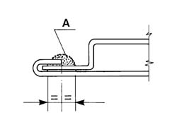
Applying a bead of SIKAFLEX 221 SIKA (*) polyurethane sealant of the shape and in the position illustrated in the diagram;
Leave the sealant to dry for 24 hours at ambient temperature (20 ° Χ) ο 40 μινυτι α 60 ° Χ;
Carrying out the normal painting cycle for the component. Apply sound deadening product or stone chipping paint to the outer parts replaced or repaired, as necessary.
(*) Alternatively, use a similar 3M product or other equivalent products, following the supplier's instructions.
Example of sealant application
A - Sealant
| When using chemical products, scrupulously observe the safety instructions on the safety card that the supplier is bound to deliver to the consumer. |