





|






|
|
| Service News | ||
|
|
Alfa various models
Version: all models |
|
|||
| 5530 B 000 AA |
BATTERIES
Instructions for correctly checking the battery charge state - Network information |
|||

|
Cancels and replaces SN 55.05.11 of 21/03/2014. |
The following table gives the instruments recognised by FCA and their use:
|
Name |
Use |
Part Number |
Instrument replaced, no longer standard |
|
Midtronics EXP 813 FCA |
Charge state check of the following batteries: Lead (Pb) flooded, Pb Heavy Duty, Pb AGM, Pb AGM Spiral |
2000037000 |
Midtronics XL513 |
|
Midtronics GRX 3228 FCA |
Integrated instrument for checking the charge state of the following batteries: Lead (Pb) flooded, Pb Heavy Duty, Pb AGM, Pb AGM Spiral |
2000035900 |
Midtronics GR-1 240 |
|
CTEK MXS 25000 FCA |
Instrument for recharging Lead (Pb) flooded, Pb Heavy Duty batteries. Not to be used for Pb AGM and Pb AGM Spiral batteries |
2000036900 |
ISEAT CB-1 |
|
FCA UNIVERSAL BATTERY CHARGER |
Recharger for the following batteries: Lead (Pb) flooded, Pb Heavy Duty, Pb AGM, Pb AGM Spiral |
2000039600 |
CTEK MXS 10 FCA (upgradable, see APPENDIX 3) |
In APPENDIX 1 there is a description of the instruments and their specifications. For further information, refer to the instruments’ instruction manuals.
Other equipment can only be used to recharge the battery, as an alternative to those listed in the table, on condition that they comply with the minimum requirements given in APPENDIX 2.

|
USING INSTRUMENTS THAT DO NOT MEET THE MINIMUM REQUIREMENTS FOR RECHARGING BATTERIES, DOES NOT ALLOW NOR GUARANTEE RECHARGING THE BATTERY CORRECTLY AND COULD SERIOUSLY DAMAGE THE CAR’S ELECTRICAL/ELECTRONIC COMPONENTS. |
BATTERY TYPES
Fig. 1 below shows a diagram of the various types of Lead (Pb) batteries mentioned in this Service News.
The type is always shown on the battery’s label.
Fig. 1 – Types of lead batteries
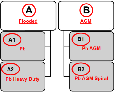

A – Flooded – Free electrolyte
A1 – Pb - For standard applications
A2 – Pb Heavy Duty - For Start&Stop applications
B – AGM (Adsorbed Glass Mat) – With absorbent material between the plates
B1 – Pb AGM - with flat plates - For standard and Start&Stop applications
B2 – Pb AGM Spiral - with spiral plates - For standard and Start&Stop applications
CHARGE STATE CHECK
PRELIMINARY VERIFICATION CONDITIONS
Before connecting the instrument and performing the diagnosis, make sure that the following conditions are met:
On the vehicle:
- engine off
- no electrical devices on, except for permanent key-off loads (e.g. the clock)
- no recharging system DTC errors in the control units
On the instrument:
- software updated to the latest release (see APPENDICES 3, 4 and 5)
- leads, clips and connectors in good condition
For all models in which the battery is easily accessible, check also that:
- that battery has no external damage
- the battery terminals are clean (otherwise, clean them e.g. with a stiff brush)
POWERING THE INSTRUMENTS
- GRX 3228 FCA: connect the equipment to a socket (220 V AC power) and turn the ignition switch to ON.
- EXP 813 FCA: turns on automatically after the clips are connected correctly.
CONNECTING THE INSTRUMENTS
For all models in which the battery is easily accessible:
It is recommended to check the battery charge state by connecting the instrument directly to the battery terminals, leaving it connected to the car’s electrical system.
|
|
At the end of the check procedure, make sure that the clamps are tightened properly to the battery terminals. |
For all models in which the battery is not easily accessible:
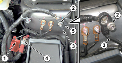
All battery charge and recharge state checks MUST be made with the battery earth lead (3 - Fig. 2) disconnected from the car’s negative dummy pole, as follows:
- Remove the earth lead fixing nut (2).
- Disconnect the battery earth lead (3) from the negative dummy pole and reconnect it to the earth pin through the insulating hole (5) and lock it in position with the same nut (2).
- Open the cover (1) on the dummy positive pole (4).
Fig. 2 – Example picture of a Fiat Freemont
|
|
At the end of the check procedure: • close the cover (1) on the dummy positive pole (4); • remove the earth lead fixing nut (2); • pull the earth lead (3) out of the insulating hole (5), reconnect it to the negative dummy pole and lock it in position with the nut (2), tightening it to a torque of 2.8 daNm. |
Use the leads in the kit to connect the instruments as follows:
- Red clip connected to the positive battery terminal (or to the positive dummy pole)
- Black clip connected to the negative battery terminal (or to the negative dummy pole)
The lead clips must be connected correctly; an incorrect connection could cause the following messages:
- On the EXP 813 FCA – CHECK CONNECTIONS
- On the GRX 3228 FCA – CHECK TERMINAL CONNECTIONS
If the leads are connected with the incorrect polarity, the tester will display the following message: TERMINALS REVERSED (the GRX 3228 FCA also emits an alarm signal).
CONFIGURING THE INSTRUMENTS FOR THE CHARGE STATE CHECK
In the main menu, use the LEFT and RIGHT arrows to select “BATTERY TEST” / “DIAGNOSIS” (battery icon on the display) and proceed as follows:
1. Use the UP and DOWN arrows to select the TEST LOCATION:
- BATTERY TERMINAL (A)
- STARTER TERMINAL (B)
2. Press the NEXT button to continue.
(A) - If BATTERY TERMINAL was selected, proceed as follows:
1. Select the battery location:
- OUTSIDE THE VEHICLE
- IN THE VEHICLE
2. Press the NEXT button to continue.
3. Select the BATTERY TYPE:
- NORMAL - Flooded (Pb and Pb Heavy Duty)
- AGM - AGM with flat plates (Pb AGM)
- SPIRAL - AGM with spiral plates (PbAGM Spiral)
- GEL - Pb with gel electrolyte (not normally used)
4. Press the NEXT button to continue.
5. Select the NOMINAL UNIT (TEST STANDARD) following the indications given on the battery’s label, according to the following table:
|
Standard given on the battery |
Standard to select on the instrument |
|
IEC |
IEC |
|
EN |
EN (or EN1) |
|
EN2 |
EN2 |
|
EN2 - SAE (with the same current value) |
EN2 |
|
EN2 - IEC (with the same current value) |
EN2 |
6. Press the NEXT button to continue.
7. Select the POWER (current) relative to the selected standard as given on the battery’s label.
8. Press the NEXT button to continue.
(A) - If STARTER TERMINAL was selected, proceed as follows:
1. Select the CAR BRAND:
- FIAT
- CHRYSLER
- DODGE
- LANCIA
2. Press the NEXT button to continue.
3. Select the CAR MODEL:
One or more options are available, depending on the previously selected manufacturer.
4. Press the NEXT button to continue.
5. Select the BATTERY VALUE:
It may not be required for some models, if they are equipped with a single type of battery.
6. Press the NEXT button to continue.
|
|
The instruments must be configured correctly, setting the battery’s rated values and test standards, as given on its label. |
Depending on the instrument, proceed as follows:
Only on the Midtronics EXP 813 FCA
- Measure the TEMPERATURE by putting the sensor about 5 cm away from the battery. As soon as temperature reading stabilises, press NEXT.
- During the test, the display shows TEST IN PROGRESS and a stopwatch icon.
|
|
The instrument could ask if the test is being performed before or after charging the battery. If a complete recharging cycle was not performed on the battery, select BEFORE CHARGING. Press the NEXT button to continue. |
- At the end of the test, the display shows the result (Fig. 3); it is possible to scroll through the screens using the UP and DOWN arrows.
- To print the results, press the PRINT function key
- To return to the Main menu, press the END function key
Fig. 3 – Battery check result on the EXP 813 FCA
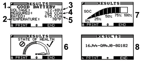
1 – Battery test result
2 – Temperature
3 – Measured voltage
4 – Measured current
5 – Rated current
6 – State of health
7 – Charge state
8 – Test code
Only on the Midtronics GRX 3228 FCA
The instrument automatically proceeds sequentially to:
- charge state check
- charge (if necessary)
- final check after recharging
While charging, the following parameters are displayed:
- charging voltage
- charging current
- remaining charge time
- charge amount supplied to the battery in Ah
At the end of the test, the display shows the result (Fig. 4); it is possible to scroll through the screens using the UP and DOWN arrows.
- To print the results, press the PRINT function key
- To return to the Main menu, press the EXIT function key
Fig. 4 – Battery check result on the GRX 3228 FCA
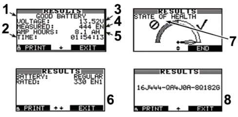
1 – Battery test result
2 - Total charging time
3 – Measured voltage
4 – Measured current
5 – Charging current
6 – Rated battery data
7 – State of health
8 – Test code
TEST RESULT AND REPAIR OPERATIONS
Depending on the test results, perform the operations in the table below:
|
MIDTRONICS READING |
OPERATION |
|
Good battery |
No operation. |
|
Recharge battery (EXP 813 FCA only) |
Completely recharge the battery using the instruments recommended by FCA and then perform the diagnosis again. |
|
Charge and Retest (EXP 813 FCA only) |
Completely recharge the battery using the instruments recommended by FCA and then perform the diagnosis again. |
|
Change battery |
Replace the battery with a new one, referring to the spare parts catalogue for the specific chassis. |
|
Faulty cell |
Replace the battery with a new one, referring to the spare parts catalogue for the specific chassis. |
|
Battery too hot (GRX 3228 FCA only) |
Leave the battery to cool down and then perform the diagnosis again. |
|
Frozen battery |
Leave the battery to thaw and then perform the diagnosis again. |
|
|
If the test results confirm the need to replace the battery, a test MUST be performed on the new battery, to ensure optimal charge conditions. |
CLAIM FORM DATA
For the battery checks and eventual replacement to be done under warranty, it is mandatory to attach all the result print-outs from the diagnosis equipment to the repair order, as described in this Service News.
The result print-outs must contain at least the following data:
- date and time
- test result
- measured voltage
- measured current
- battery’s rated current and the relative standard
- indication of previous recharging performed
- location of the battery (in the vehicle, outside the vehicle)
- position of the clamps (battery terminals, dummy poles)
- type of battery (normal, AGM, spiral)
This information must be included in the message field in the Claim Form in the form of the test code (see ref.8 - Fig.3 and ref.8 - Fig.4). It is possible that paper copies of the print-outs could be requested during the claim assessment.
If the information is incomplete, incorrect or if there is evidence of failure to apply the procedure described in this Service News, FCA reserves the right not to reimburse the repair costs.
|
OPERATION |
OPERATION CODES |
TIME |
|
Preliminary diagnosis + battery replacement |
5530B10 |
defined in the Work Schedule |
|
For each battery test, following the first one |
0520G20 |
defined in the Work Schedule |
APPENDICES
The attached file contains the following appendices:
- Appendix 1 – Description and technical specifications of the instruments
- Appendix 2 – Minimum requirements for battery chargers
- Appendix 3 – CTEK MXS 25000 FCA upgrade
- Appendix 4 – Midtronics EXP 813 FCA software upgrade
- Appendix 5 – Midtronics GRX 3228 FCA software upgrade
To open and download the file, select the corresponding icon.

|