





|






|
|
| Service News | ||
|
|
Alfa MiTo
Version: all versions M.Y. 2013 |
|
|||
| 5570 1 821 RD |
USB PORT
Failed operation - Service Solution |
|||

|
Cancels and replaces SN 55.10.15 of 03/04/2015 |
CLAIMED FAULT
Failed operation of devices connected to USB port.
TECHNICAL CAUSE
Electric connection between USB port and Uconnect device.
OPERATIONS AT THE DEALERSHIPS
DEALERSHIP BEHAVIOUR STANDARDS TOWARDS THE CUSTOMER
- When this problem is reported and confirmed, reassure the customer that it can be solved by restoring the correct connection between USB port and Uconnect device.
- After the operation, show the Customer what has been done and make sure he is satisfied.
Service Solution
Once the claimed fault is confirmed, check the electric connections and replace the cable connecting the USB port to the Uconnect device, according to the Operating Cycle below.
OPERATION CYCLE
UBS port and cable check
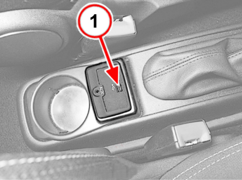
- Check that the USB port (1 - Fig. 1) is not damaged. Try inserting a USB flash drive correctly operating on other devices and make sure it can be plugged in completely.
FIG. 1

If the USB port is not damaged, continue by checking the connection cable between USB port and Uconnect device as follows:
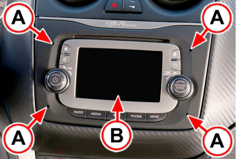
- Insert the special tools in the holes (A - Fig. 2) to disengage the internal retainers and then carefully extract the Uconnect device (B).
|
|
Be careful not to damage the dashboard lining; arrange the protections to prevent the Uconnect device from causing scratches and/or cuts. |
FIG. 2
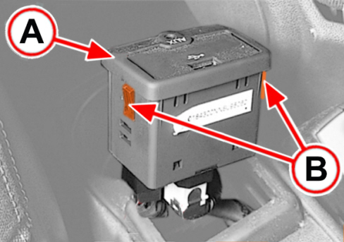
- Using a knife (tool 1823014000), extract the USB/AUX port support (A - Fig. 3) by releasing it from the side retainers (B).
FIG. 3
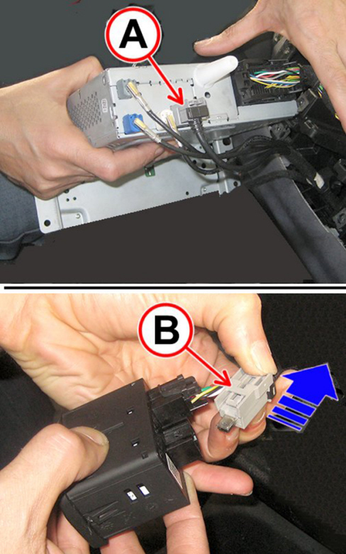
- Check that both USB cable connectors are correctly connected to the Uconnect device (A - Fig. 4) and to the USB port (B - Fig. 4), thus excluding that the fault is caused by a missing or loose connection.
- Disconnect the USB cable connectors from Uconnect device (A - Fig. 4) and the USB port (B - Fig. 4).
- Check integrity and continuity/insulation of the USB cables and connectors. Replace the entire cable as shown in the following chapter in presence of faults.
FIG. 4
USB cable replacement

|
If the entire USB cable is replaced with a new one, check on DRS whether removed parts (i.e. USB connectors with cut and removed cable pieces) must be returned. Please note that the warranty coverage for the operation will not be paid in case of failure to return removed connectors (where required by rules and regulations for your market). |
- Remove the central tunnel lining (referring to Technical Service Manual procedure Op. 7040L20).
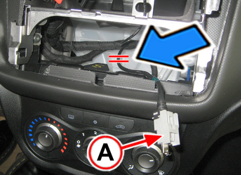
- Cut the connector cable connected to the Uconnect device (A - Fig. 5), as shown in figure, and tape it to isolate it and constrain it to the existing cables.
FIG. 5
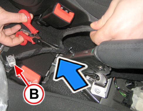
- Cut the connector cable connected to the USB port (A - Fig. 6), as shown in figure, and tape it to isolate it and constrain it to the existing cables.
FIG. 6
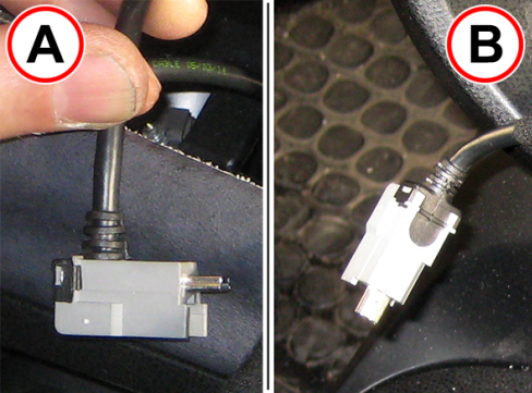
- Take a new USB cable (71777315) from Spare Parts.
|
|
The connectors on the ends of the USB cable are mutually different: the cable exits the connector to be connected to the USB port (A - Fig. 7) at a perpendicular angle (90°), while the cable exits the connector to be connected to the Uconnect device (B - Fig. 7) axially (in line) with the connector. |
FIG. 7
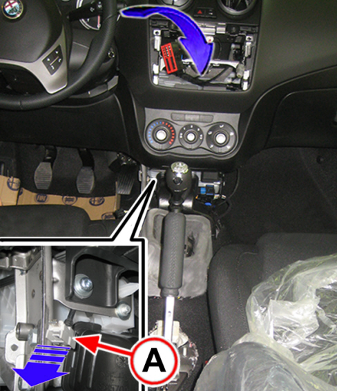
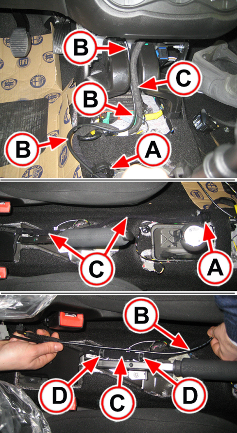
- Insert the connector to be connected to the USB port (A - Fig. 7) in the Uconnect device compartment, making it slide downwards until it exits from behind the bracket (A - Fig. 8).
FIG. 8
- Open the band (A - Fig. 9) located by the side of the gear stick.
- Tape the new USB cable (B - Fig. 9) to the existing tunnel wiring (C) to near the bands (D) by the side of the handbrake.
- The bands (D - Fig. 9) must not be removed; near the handbrake lever, constrain the USB cable (B) to the wiring (C) by means of two strip bands (14560187).
- Close the band (A -Fig. 9).
FIG. 9

|
Make sure that the wiring in the Uconnect device compartment is arranged correctly to install the Uconnect device without problems and so as to avoid noise or interruptions of continuity later caused by excessive bending or pinching between devices. |
- Connect the USB connector to the Uconnect device.
- Refit the Uconnect device by inserting it in its housing to engage the internal retainers.
|
|
Make sure that the tunnel wiring is correctly arranged so that the tunnel lining can be installed without problems and that no noise or interruptions of continuity occur in case of incorrect fastening, excessive bending or pinching. |
|
|
Any extra length of the USB cable must be appropriately wound and taped to the existing wiring and arranged inside the tunnel lining under the USB port. |
- Refit the central tunnel lining (referring to Technical Service Manual procedure Op. 7040L20).
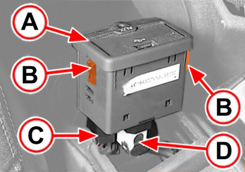
- Connect the electric connections of the Aux ports (C - Fig. 10) and USB (D).
- Insert the USB/AUX port support (A - Fig. 10) in its housing and engages its two side retainers (B).
FIG. 10
PARTS AVALABILITY
|
Version |
Description |
Part No. |
Q.ty |
|
All models in question |
USB Cable |
71777315 |
1 |
|
All models in question |
Cable ties |
14560187 |
2 (*) |
(*) Each pack contains 20 cable ties
CLAIM REPORT DATA
|
Version |
Operation |
Part |
Anomaly |
Position |
Time allowance |
|
All models in question |
5570182 |
1 |
RD |
- |
0.45 |