





|






|
|
| Service News | ||
|
|
Alfa MiTo
Version: MY 2013 with Kenwood radio |
|
|||
| 5570 1 771 GF |
RADIO
Radio installation intervention – Information to the network |
|||

|
Cancels and replaces SN 55.09.13 of 07/08/2013 for updates of the chapter Warranty - Replacements. |
OPERATIONS IN PRODUCTION
For the Model Year 2013 versions and for the Italian market only, the Optional 082 (radio setup system) and the Kenwood radio with removal front panel can be ordered (optional for versions/markets, where provided).
For these vehicles, the plant:
- installs the complete setup (loudspeakers, aerial and connection cables) but not the radio
- installs the glove compartment instead of the radio
- supplies the aerial power supply adapter (Phantom Box) putting it in an envelope in the luggage compartment, together with the aerial to be screwed on the roof mount.
OPERATIONS IN NETWORK
The radio kit is shipped directly to the selling Dealership for the PDI installation of the radio replacing the glove compartment
The kit contains the following components:
- Radio with removable front panel
- Radio mounting bracket
- Decorative frame
- Electrical connection harness
- Tools (keys) to remove the radio
- Owner handbook
OPERATION CYCLE
Install the vehicle radio available in the kit, according to the Operating Cycle below.
- Disconnect the negative battery terminal.
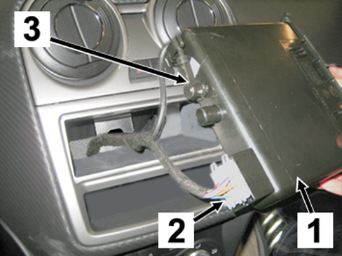
- Remove the glove compartment (1 - Fig. 1).
- Detach the radio wiring connector (2 - Fig. 1) and the radio aerial connector (3) from their seats.
Fig. 1

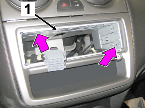
- take the mounting bracket (1 - Fig. 2) supplied in the vehicle radio kit and fit it in the radio compartment, then engage it using the securing tabs.
|
|
Keep the radio and aerial wiring out of the compartment, as shown, for the following connection of the radio. |
Fig. 2
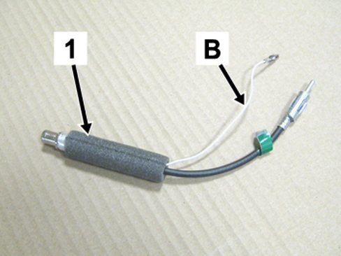
- Take the aerial power supply adapter (1 - Fig. 3) and identify the aerial power supply cable (B).
Fig. 3
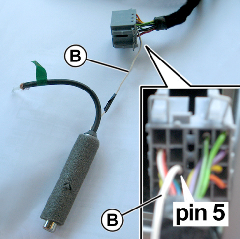
- Fit the aerial power supply cable (B – Fig. 3) in pin 5 of the radio harness as shown in Fig. 4.
Fig. 4
• connect the connections for the vehicle wiring (1 - Fig. 5) to the radio harness (2).
• connect the aerial cable (3) to the aerial power supply adapter (4).
Fig. 5
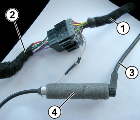
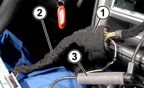
- Wrap the connection (1 – Fig. 6) and the radio harness (2) with felt adhesive tape to eliminate possible noises.
- Connect the radio harness (2) and the aerial power supply adapter (3) to the dedicated connections on the radio.
Fig. 6
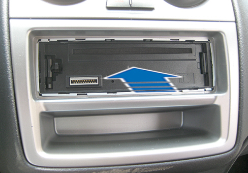
- Fully fit the radio in place (Fig. 7) until it clicks and is securely connected.
Fig. 7
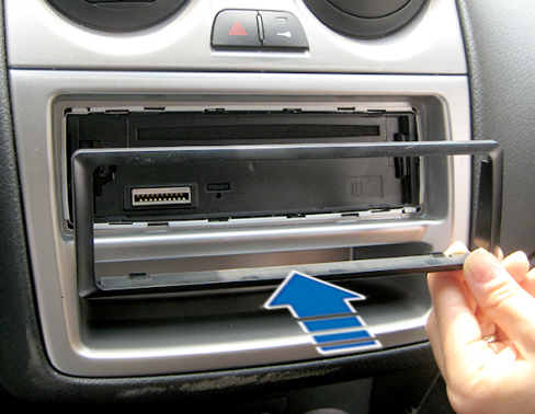
- Apply the decorative frame (Fig. 8) supplied with the radio.
Fig. 8
- Apply the radio control front panel (Fig. 9).
Fig. 9
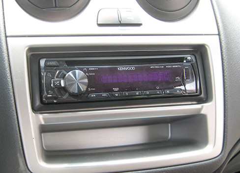
- Reconnect the battery negative terminal and make sure that the radio works properly.
|
|
The owner handbook and the removal tools in the radio package kit must be handed over to the Customer with the removed glove compartment. |
WARRANTY - REPLACEMENTS
The warranty for this radio type will be supplied by Lineaccessori, the reimbursement requests must submitted:
- with technical fault procedure (CSPS) for repairs performed in Italy
- using the expense code M03 for repairs performed abroad
For any replacement, order the new radio through standard CSPS.
INTERVENTION CODE
The code for signalling the intervention made and the relevant allowed time are specified in the table below.
|
Version |
Operation |
Part |
Fault |
Position |
Time allowance |
|
All models in question |
5570177 |
1 |
GF |
- |
0.25 |